The D2 was present in the original circuit so I put it there as well to make it similar. I think its to dissipate any inductive or current spike when the circuit is first initiated.
Have you checked the polarity of D2? If it is backward, your transistor will get very hot if D2 survives.
The beta of a saturated transistor is much less than it is when Vce>>0V. If you look at the datasheet of almost any BJT, you will find that Vce(sat) is specified for Ic/Ib=10. In your circuit, Ic≈10mA. Therefore, Ib needs to be ≈1mA. Hence the 18k base resistor.
You circuit might work with 100k, but if you built 1000 of them, some of them might not work. Good engineering practice dictates Ic/Ib≈10 (or less) to ensure saturation.
Attached is the Vce(sat) spec for 2N3904.
When the darlington is linear so it is not saturated and has a voltage of 5V between its collector and emitter then its hFE (DC current gain) at 200mA is 10000.
The datasheet also shows that it saturates fairly well with much more base current than above.
You want the darlington in your circuit to saturate. Then its hFE should be calculated to be no more than 500.
The same applies to ANY transistor. Look at the saturation spec of a 2N3904 in post #42. Its hFE is calculated to be only 10. But when the 2N3904 is not saturated so it has plenty of collector to emitter voltage then its hFE is from 100 to 300.
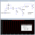
I found an incandescent lamp model on the LTspice Yahoo group. I ran a simulation on your circuit with the input at 1Hz, 50% duty cycle. The average power dissipation of your Darlington was 1.0 Watts! The lamp model is obviously not perfect, but this is evidence enough for me.
I also ran the sim at 10Hz, 50%, and the dissipation dropped to 500mW (still too hot to touch). At 0.1Hz, 50%, the average dissipation dropped to ≈100mW.
If anyone wants to run the sim in LTspice, I have included all the required files (I think). I have included the MPSW45 model as a .txt file. You will want to change the extension to .sub before saving it in your SUB folder.
Note to moderators: It would be nice to allow the .sub extension for attachments. I suppose the admin has to make this change.
When the darlington is linear so it is not saturated and has a voltage of 5V between its collector and emitter then its hFE (DC current gain) at 200mA is 10000.
The datasheet also shows that it saturates fairly well with much more base current than above.
You want the darlington in your circuit to saturate. Then its hFE should be calculated to be no more than 500.
The same applies to ANY transistor. Look at the saturation spec of a 2N3904 in post #42. Its hFE is calculated to be only 10. But when the 2N3904 is not saturated so it has plenty of collector to emitter voltage then its hFE is from 100 to 300.
Saturation is needed to keep the transistor cool, but I don't think that is the intention of the circuit. If it were, there would be no need for the RC filter or the emitter resistor.
So you do see that it does get very hot. Can you try the same with MPSW13 and see if there is any difference. I don't know how to create new models on LTSpice.
Q1 is working as a switch. So it will work in Saturation or cutoff region. The original design set the Q1 base never higher than few volts.
In your replacement, Q1 will be charged to 18V. And will never go to Saturation. So it's an amplifier and will burn. Fix your control ckt from R2 to the left.
Please refer to MPSW45 figure 9, 10 and MPSW13 figure 3,4.
Q1 is working as a switch. So it will work in Saturation or cutoff region. The original design set the Q1 base never higher than few volts.
In your replacement, Q1 will be charged to 18V. And will never go to Saturation. So it's an amplifier and will burn. Fix your control ckt from R2 to the left.
Please refer to MPSW45 figure 9, 10 and MPSW13 figure 3,4.
Hee, hee. When I tell something like that to a NOOB then I am banned for a week. Maybe your word Respectfully might be the difference. Respect for a NOOB??
Most NOOBs don't have a clue.
There should be a special website for NOOBs.
And if the NOOB is from a foreign country then ...... never mind.
Hee, hee. When I tell something like that to a NOOB then I am banned for a week. Maybe your word Respectfully might be the difference. Respect for a NOOB??
Most NOOBs don't have a clue.
There should be a special website for NOOBs.
And if the NOOB is from a foreign country then ...... never mind.
Yeah, I was a little concerned... still am, for that matter. It just irks me when we have been chewing on a very complex problem (incandescent bulb hot vs cold resistance and thermal time constant, mainly) for a week, and a 2-poster comes in who probably has not read the entire thread and confidently makes statements that are wrong.
The US is my neighbour. Most of us speeky zee same language but I have difficulty understanding a southern drawl, a hill-billies accent and some slang in New York.
The US is my neighbour. Most of us speeky zee same language but I have difficulty understanding a southern drawl, a hill-billies accent and some slang in New York.

 Facebook
 Google
 GitHub
 Linkedin