Damaged contactor

Thread Starter

cmartinez

Joined Jan 17, 2007
8,253
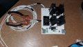
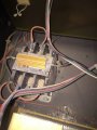
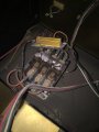
A friend of mine owns a rather old Gerber CNC router that has a contactor installed showing severe damage from overheating. The strange thing is that a component that looks like a high capacity resistor (the one with the yellow heatsink) was installed atop the thing. Its cables look toasted and frayed.
Why is that? I do know how to replace a contactor but I don't understand the function of the resistor, especially its being installed atop the contactor. I haven't personally taken a look at the machine or the circuit itself, but I will soon. I just wanted to see if I could make a head start by asking here if anyone's seen something similar before.
@MaxHeadRoom, I've got a feeling that you could help me out with this one.
 

Attachments

Last edited:

MaxHeadRoom

Joined Jul 18, 2013
28,688
I think that was a misplaced choice of locations to place a heat-sunk resistor!
Whoever chose that place obviously did not forsee the eventual outcome, probabally nothing wrong with the contactor originally.
The resistor should have been mounted to the enclosure back plate.
What the function is is up in the air without consulting the prints.
Was this wired across a pair of contacts?
Max.
 

gerty

Joined Aug 30, 2007
1,305
Where do the wires from the resistor go? Could it be the the coil of the contactor is rated for 120v and is being fed with 220v, or some other similar mismatch?
 

Thread Starter

cmartinez

Joined Jan 17, 2007
8,253
Where do the wires from the resistor go? Could it be the the coil of the contactor is rated for 120v and is being fed with 220v, or some other similar mismatch?
Thank you both for your valuable opinions... as I've already mentioned, I've still got to take a look at the thing personally. But yes, my first suspicion was that the resistor is there to use 220VAC on a 110 VAC rated coil, to limit its current (though I doubt it, that would be a terrible design implementation) Or, as Max has just said, it's placed in a very lousy place if it is indeed performing some other function.
Whatever it is, I'll get back to you tomorrow with more info.

Thanks again!
 

MaxHeadRoom

Joined Jul 18, 2013
28,688
If the resistor is actually needed in circuit, I would definitely transfer it to the mounting panel.
Contactors are plentiful now so make sure it has the right coil voltage.
Max.
 

Johann

Joined Nov 27, 2006
190
Could be that the coil is DC? In some contactor designs (DC and sometimes high voltage AC) use was made of what is called an economizing resistor. The resistor is in series with the coil, but in parallel with a normally closed (N.C.) contact of the contactor. When power is initially applied to energize the coil, the applied voltage appears across the coil only and causes the rapid closure of the contactor, however, when it closes, the N.C. contact opens and effectively puts the coil in series with the resistor. This limits the power consumption of the coil. Once pulled in, only a weak magnetic field is needed to keep the armature in position.
 

Thread Starter

cmartinez

Joined Jan 17, 2007
8,253
Could be that the coil is DC? In some contactor designs (DC and sometimes high voltage AC) use was made of what is called an economizing resistor. The resistor is in series with the coil, but in parallel with a normally closed (N.C.) contact of the contactor. When power is initially applied to energize the coil, the applied voltage appears across the coil only and causes the rapid closure of the contactor, however, when it closes, the N.C. contact opens and effectively puts the coil in series with the resistor. This limits the power consumption of the coil. Once pulled in, only a weak magnetic field is needed to keep the armature in position.
Good point. I'll check into that too. Thanks.
 

Thread Starter

cmartinez

Joined Jan 17, 2007
8,253
It seems that @Johann was right... The contactor is used to switch two lines of 120VDC (ground and 120VDC) and the middle contact is used to sustain the coil, which is being fed 40VDC through a 50Ω @ 50W resistor. The coil's resistance itself is 90Ω. The contactor's information plate has been burned and toasted and turned to dust.

I personally think it stupid to have mounted the resistor on top of the contactor, but what the heck... the thing worked fine for at least 7 years. Anyway, power to the coil is cut when an emergency stop button is pressed, and when the coil is not connected, the 40V feeding the coil drops very slowly (takes at least 20 sec for it to reach zero). That tells me that there's a power supply with some caps that need time to discharge if there's no load present.
The contacts show quite a bit of corrosion and pitting, and I suspect that's what's making the machine go berserk, since the the contactor is in charge of feeding the drivers for the servos. Also when I measured voltage immediately after the machine was switched on, I'd read 120VDC. And after 4 or 5 minutes the voltage steadily dropped to less than 80VDC, plus the servos were warming up even when at rest.

So I've got two options here
  1. Replace the contactor exactly (or as close as possible) as it is. DC coil and all.
  2. Use SSR relays instead. I'd just have to figure out how to make sure they're quickly de-energized after the emergency stop button is pressed.

I'm leaning towards option #1, since the machine is not mine and I don't want to complicate things too much. Plus I'd like to fix this thing in a single shot.
 

MaxHeadRoom

Joined Jul 18, 2013
28,688
You could always use a straight DC contactor whose coil is rated for the constant supply voltage, Telemecanique and others make them, the alternative by rights is to use the dual DC coil contactor I posted.
The former is what I would be inclined to do.
Max.
 

alfacliff

Joined Dec 13, 2013
2,458
looks like someone put a brake on the motor the contactor controls. the back of the contactor has the terminals tied together, the resistor is to introduce some "dynamic braking"
 

Thread Starter

cmartinez

Joined Jan 17, 2007
8,253
Thanks for your help, Max and Alfa. (btw the contacor switches on and off the driver card that controls the motors, and not the motors themselves)
I'm thinking about using a couple of high capacity mosfets, since I cannot find a supplier down here offering a contactor with a dc coil.
 

Attachments

MaxHeadRoom

Joined Jul 18, 2013
28,688
What is picking up the contactor?
Can you discern the reason for using a DC coil?
Is AC available for a more common contactor coil value?
Also you can get 120vdc SSR input to AC output, I know Opto22 make them.
Max.
 

Thread Starter

cmartinez

Joined Jan 17, 2007
8,253
What is picking up the contactor?
Can you discern the reason for using a DC coil?
Is AC available for a more common contactor coil value?
Also you can get 120vdc SSR input to AC output, I know Opto22 make them.
Max.
Thanks... I need a 120DC input to 120DC output. And I just remembered someone local that might have it
 

Thread Starter

cmartinez

Joined Jan 17, 2007
8,253
I thought I'd give this thread some closure and tell everyone what happened in the end.

Here's the problem's summary:
  • Needed to replace a damaged contactor in an old Gerber CNC router whose contacts were showing severe damage due to corrosion and pitting
  • The contactor's coil was being run by a 40VDC power source through a 50Ω/50W resistor that was warming up as hell
  • At first I thought that the contactor was being used to switch on and off a load that ran at 120VDC (yes, DC) but later I found that it was being used to feed four step motor drivers that run at 6VDC (stupid me... I didn't measure at how many amps, but I'm guessing it must be no more 30Amps total) ... and that explained why the machine was being affected... the crappy contacts were dropping the 6VDC source to levels that made the drivers misbehave, and the motors overheat.
Anyway, what I did in the end was build a SSR using a couple of mosfets in parallel (check the mosfet's datasheet if you want... it was definitely overkill) on the high side of the 6VDC power supply, using a circuit that I had already built and tested that was generously designed by @JDT .

And it worked flawlessly and perfectly ... THE END...

NOT QUITE.... You see... I tied both inputs, and both outputs of the MC35151 so as to drive both mosfets in parallel, and that worked beautifully, but then I thought I'd like to see an LED light up when the mosfets were active, and connected the LED's anode through a 1.8K resistor to the mosfet's gate, and the cathode to the source... and it didn't light up.... the driver works fine (optoisolator and all), and the mosfets turn on and off when I tell them to, but the LED won't light up connected that way.... why is that? Isn't the gate receiving 12V (relative to the source) from the MC35151, and shouldn't that power up the LED?
 
Last edited:
Top