D Flip Flop Frequency Divider.

Thread Starter

Stantser

Joined Jul 5, 2016
4
Good day everybody, I am trying to create a D FF frequency divider using transistors.
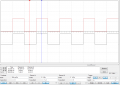
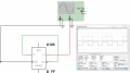
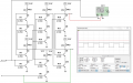
In the pictures below I used a standard flip flop and one made out of logic gates, and those 2 provided the results that I seek. However, when I attempted to make one out of transistors, I managed to fail pretty hard. Where did I go wrong in the third picture ? I am 95% certain its hooked up correctly, maybe it is not outputting 5V and 0V ? Could anyone please take a look at it ?
 

Attachments

Sensacell

Joined Jun 19, 2012
3,453
Trickier than you might think.
When I teach students about digital logic, we build this circuit to learn what a flip-flop is.
The neat trick here is the way the circuit steers charge into the capacitors to make the trigger pulse unequally bias the transistor into toggling.


flop.png
 

crutschow

Joined Mar 14, 2008
34,470
Trickier than you might think.
When I teach students about digital logic, we build this circuit to learn what a flip-flop is.
The neat trick here is the way the circuit steers charge into the capacitors to make the trigger pulse unequally bias the transistor into toggling.
View attachment 108770
Yes, that's an interesting circuit, which is a Toggle Flip-Flop (not a D-type).
Basically the diodes are biased by the state of the flip-flop so the negative trigger pulse to the capacitors goes through the diode to the base of the transistor that's ON, which shuts it off. This then applies a positive voltage through the 47k resistor to the opposite transistor base, turning it ON and causing the circuit to flip states (toggle).
 

Kjeldgaard

Joined Apr 7, 2016
476
I have not analyzed the transistor version fully, but immediately I see a mismatch between the base and collector resistances.

What will happen if all base resistors changed from 4K7 to 47K or maybe 100K?
 

Thread Starter

Stantser

Joined Jul 5, 2016
4
Thank you for the replies everyone.
While I do appreciate the alternative toggle circuit, I right now am more interested purely in the transistor logic and why its not working, I would like to dabble into more logic later on, sadly I am already failing at this easier one.
I took a look at the circuit again, everything seemed to be connected correctly. And as for Kjeldgaard, replacing the resistors made the logic more pronounced, from near 4,6V (up from 2,1V), however, the output is still DC level.
 

Thread Starter

Stantser

Joined Jul 5, 2016
4
Actually, there seems to be a pretty severe drop in voltage across the resistors and transistors. I boosted the VCC to 10 V, it now gives us a proper output, however, it does not divide.
 

Attachments

Sensacell

Joined Jun 19, 2012
3,453
For the record, the way you have drawn the schematic is painful to read, this limits my enthusiasm to spend time unraveling what is going on there.

A schematic is a means of communication, you will get more out of this if you lay it out in a way that makes it easier to understand.
 

Thread Starter

Stantser

Joined Jul 5, 2016
4
Anyways, I got it fixed, the circuit works, human error, as usual.
With a bit of probing around, found that R19 and Q13 were not connected at all, that caused my output at Q11 be always high.
 
Top