Facebook
 Google
 GitHub
 Linkedin
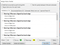
I do not get any error, just warnings related to silkscreen cutting. I updated the net class looking at the manufacturer reference data. You can have a look at PCBway manufacturing capabilities or follow my net class screenshotHi T,
Do you get this result when you run the DRC?
C
Attachments
-
 28 KB Views: 4
 -
 5.5 KB Views: 4


")