A patch panel will be simple for anybody to wire without a schematic drawing. I used to do it building tube type amplifiers. But one certainly need the pin-out of each tube.
Good question, in this setup, as I understand it, I'm not isolating the MOSFET grounds between amps because it's not necessary for how my switching is designed.
Each amp’s speaker output (L+, L−, R+, R−) runs through its own dedicated set of MOSFETs (IRF3205s), and I'm switching BOTH the positive and negative lines per channel. So, I anticipate that the speaker outputs are completely isolated from each other at the signal level and there should be no shared connections between amps.
I’m not tying any speaker negatives together, and I’m not using the MOSFETs to switch signal grounds, only floating speaker outputs. As long as each amp’s speaker output is isolated, I should be fine.
If my logic is off, I would need a correction for the anticipated build.
A patch panel will be simple for anybody to wire without a schematic drawing. I used to do it building tube type amplifiers. But one certainly need the pin-out of each tube.
This is not piling on; it is a serious question: Do you really expect to get *circuit* advice on a site with *circuits* in the title, in a forum called "Analog & Mixed-Signal Design", without showing us your *circuit*?
Paraphrasing Rear Admiral Joshua Painter,
"Engineers don't take a dump, son, without a schematic."
The isolation between amplifiers is achieved because each amplifier's speaker outputs (L+ L− R+ R−) are routed through their own dedicated MOSFETs. In theory, there’s no electrical connection between the drains of different amps. So, every amp gets its own set of 4 MOSFETs (one per speaker line), and those MOSFETs are only active when selected via the cam switch.
So while all the MOSFET sources go to a shared bus (like the speaker relay board), the drains are isolated simply because they’re physically separated and each amp's output only connects to its own MOSFETs, and those never tie together unless manually "bridged".
This is not piling on; it is a serious question: Do you really expect to get *circuit* advice on a site with *circuits* in the title, in a forum called "Analog & Mixed-Signal Design", without showing us your *circuit*?
Paraphrasing Rear Admiral Joshua Painter,
"Engineers don't take a dump, son, without a schematic."
I might be totally off on this but my logic is that amps are isolated because each one's speaker output runs through its own set of MOSFETs. There will be 96 total MOSFETs. When a MOSFET is off, it should act like an open switch—no connection, no current. I assume that even though all the sources go to a shared speaker line, only the selected amp’s MOSFETs are turned on, so only one amp is ever connected at a time. Am I off on this? Is there a better way to accomplish this?
MOSFET are controlled via a voltage between gate and source.
Unless you have independent and isolated power supplies for each individual MOSFET, how do you achieve isolation (and ground loops) between each individual amp? I, like others, fail to visualize it.
That is the reason people ask for the schematics. Those are the circuit “maps” that allow anybody to visualize the current flow through all the different nodes.
A circuit description is not sufficient.
To the speakers, yes, but the sources are all connected together which means one output of all the amps are connected together, which is likely a recipe for disaster.
To the speakers, yes, but the sources are all connected together which means one output of all the amps are connected together, which is likely a recipe for disaster.
Since you would need to totally isolate the connections to each MOSFET, it's likely easier to use a double-pole mechanical relay for each amp.
Alternately a solid-state relay with a bipolar MOSFET DC output (not AC which use SCRs) would work (example).
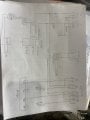
As I am doing the schematic, you are correct, I do NOT have enough MOSFETs to isolate the grounds. I would need 8 MOSFETS per amp. That gets a little too much......
To the speakers, yes, but the sources are all connected together which means one output of all the amps are connected together, which is likely a recipe for disaster.
Since you would need to totally isolate the connections to each MOSFET, it's likely easier to use a double-pole mechanical relay for each amp.
Alternately a solid-state relay with a bipolar MOSFET DC output (not AC which use SCRs) would work (example).
I don't know if anyone else has pointed out this, but a MOSFET had an internal diode , called a body diode, between its drain and source. This is a consequence of the manufacturing process. Depending on the size of the FET, its Vf can be fairly high, as in over 1 V. But it will conduct above that level even when the FET is "off". The solution is two FETs back-to-back (source to source).
I was going to suggest an optoMOS (or some other brand) because it solves two problems - galvanic isolation and that body diode thing. One possible issue is that these were developed to replace relays in modems, so the audio fidelity might be lacking.
To be clear, there are at least two. First, there is no GND at the power supply, so *none* of the digital and analog signals have a reference potential / return current path / whatever. Second, you show two FET sources connected together (good) but not connected to anything else (bad). Third, there is a high voltage supply that needs to be referenced to the low voltage control circuits.
AND someone is bound to say this - you have an "offline" supply for the nixie tubes - one with no isolation from the AC mains. This is the dictionary picture of lethal.
 Facebook
 Google
 GitHub
 Linkedin