Facebook
 Google
 GitHub
 Linkedin
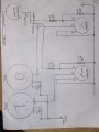
What do you think of a AQV252G PDIP-6 HE? Seems like it should be up to 75 watts/8 amp.That would allow a max average of 11.5W into an 8Ω speaker load.
It would likely be enough for a typical music listening level, but may not sufficient for loud rock at a party.
Custom Audio Amplifier and Receiver Selector Swtich
- Thread starter r8f1k
- Start date