 Facebook
 Google
 GitHub
 Linkedin
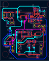
I found a design for a curve tracer online that I have adapted for my needs and available parts. I have built this exact schematic on a breadboard, using through hole parts and only one filter circuit. On the breadboard it works as expected. For the breadboard I got it working by using an LM 358 to get the split supply and an TL074 as the op amp. For the SMD build I used only TL072 while keeping everything else the same.
I have checked the supplies of all op amps. I have checked for broken traces, misplaced parts and all other "reasonable mistakes"
When I probe U2's pin 1 I was expecting a roughly 700 mv Sine wave. I get a square wave that is not bipolar. This suggests to me that there is an issue with the power supply or the filter circuit. What unsettles me is the fact that the THT version on the breadboard is working.
My question is: Is there a reasonable mistake that I have made somewhere that can be fixed without scrapping the whole design or should I just throw it out and replicate the through hole version?
Thank you. This is my first time ever doing SMD.
Attachments
-
7.9 KB Views: 7
-
25.2 KB Views: 16
-
 65.7 KB Views: 6


