I'm sorry - I'm wading into this a bit late, and I must confess I haven't read every word that has been said by everybody in the thread. However, I have read all the initiator's comments.
It seems to me that Ohms Law has not yet become second nature to you. Voltage and current are intimately bound together. You can't have one without the other. If you go back to the diagram in post #27, where does that input current, "I(in)" come from? I may be misunderstanding you, and I hope I'm not teaching Grandma to suck eggs here, but you can't just manufacture a current like that without a voltage being involved. The current amplifier you have drawn has an input resistance. Let's say, for example, that the input resistance is 10k. If you put a voltage of 1V on the input, then the current that flows into the amp, by Ohms Law, is I = V/R = 1/10,000 amps = 100uA. When designing, you may take the current into account to see what is happening in other parts of the circuit, but you can't put a current on the input without putting a voltage there. The current that flows is simply a consequence of the voltage. As voltages are much easier to measure, design usually hinges around them. You measure the voltages and work out the current if you need to know it for some reason. If the op amp had no output resistance and you connected a short circuit from its output to ground, then the current that would flow through that short circuit would be anything that the power supply could provide - but we know that wouldn't happen. Something would produce smoke. In fact, the op amp DOES have an output resistance, which limits the current that the op-amp can produce. In the case of a 741, the output resistance is about 75 ohms, and you can consider that as a resistor connected to the output of the amp, but inside the chip where you can't measure it. If you want to drive a LED with an op-amp, then you use the voltage that comes out of the amp to drive current through the LED - but the lesson is that you can't have current without voltage (or vice-versa)
Is this a lab exercise to establish the characteristics of an op amp, or is it for some application that requires a current out of the op-amp? If the latter, you could play with a transconductance op-amp. See the Wikipedia entry. They're not expensive.
I'm sure you know that if you apply a voltage to two resistors in series, (V ------R1-------R2------gnd) then the voltage between the two resistors is (R2/R1 x V). If R2 is inside the op-amp where you can't get at it, then you can connect R1 to the op amp and apply a known voltage then measure the voltage at the input of the op-amp to determine the input resistance - that 'resistor' inside the chip. You can do the same for the output resistance. See this link
Usually, when a design calls for a known current, it is to put it through a known resistor to derive a precise voltage, for example for a reference voltage. Another reason you may want to produce a known current is to charge a capacitor at a known rate. If you charge a cap with a constant current, the voltage across the capacitor is a linear ramp.
BTW, the two most important formulae for simple circuit design are ohms law (V = IR), and the power formula W = VI (watts = volts * amps), which you can use to determine whether a 1/4W resistor is going to be good enough, or whether you need a beefier one.
Thanks... But I think this i not related to limitations and temperature...
Here is the video of the current decaying...
@cognas I am aware of most of your words and thoughts. But this for the tips.I started this thread in a way and it already derived into several differents ways from the ones I wanted.
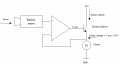
I told originally that I had an input current that was coming from a sensor and I wanted to use that current to be able to light up a LED or to drive a DC motor! And to do this I need more current than the one that the sensor outputs. So I need to amplify it. People started to suggest voltage controlled current sources and I said that I have no input voltages to control the current, I only have the current from the sensor. That why I said I have no input voltage. Well, of course I have a voltage source, but it's not my goal to use it to control the output current of a current amplifier. I know that I need a voltage on order to have a current flowing through some component. Then people suggested the transconductance OpAmp which I'm trying now.
When you say "I had an input current that was coming from a sensor", I still don't think you 'get' it. It would be possible that the sensor drives, let's say, 1mA, in which case, if your op amp has an input resistance of 1k, your sensor would produce a voltage of 1V, or if you connected it to a different amp with an input resistance of 2k, then the sensor would put 2V on its input - but I honestly don't think that's likely. Much more probable is that it produces a known voltage, rather than a known current. What kind of sensor are you using? Can you say something about it? The current going into the op amp is much more likely to dependend on the op-amp itself - very unlikely that it is dependent on the sensor.
Also, what current do you need after amplification? You say to drive a motor or LED. If you were going to directly drive a motor from an op-amp, it would have to be an unusually tiny motor.
You didn't answer the question about the nature of the work you're doing - experimental lab work, or application circuit.
This is only a personal experiment but I'm a student and therefore my knowledge is very limited. I had an idea for a small project that would use at least 2 sensors. Particle sensors or smoke sensors. But as I don't have any of those sensors, I wanted to try to light up a LED or drive a small DC motor using a motion or temperature sensor. These ones I have here at home! The job of reading the sensor and processing it's data would be done by a microcontroller, possibly AtMega328PU, and then I wanted to use the sensor current to drive the motor or light up a led, just for testing purposes. So I need to simulate the current of the sensor, and that would be my "input current" that I need to amplify!
OK. If you want to drive an LED, it gets brighter as the current through it increases, but it is quite difficult to control that current because of the VI curve of a diode (current to voltage curve - a small difference in voltage can produce a large difference in current, and can burn out the LED), so we usually make a circuit of an LED in series with a resistor, and we put that voltage across the pair. The resistor makes the current more proportional to the voltage. You can most likely drive an LED + resistor (typically 1K) directly from the op-amp.
It takes a lot more current to make a motor turn, and an op-amp will typically not produce enough current, so we have to take the voltage from the op-amp and use it to produce a current. A transistor can be used for this. The one shown below is in emitter-follower configuration, which means it is not being used as a voltage amplifier. The voltage on the emitter follows the voltage on the base, but 0.6V lower, so if the base is at 2V, the emitter will be at 1.4V. The 1.4V drives a current through the motor that is proportional to the resistance of the motor, and the necessary current flows through the transistor from collector to emitter. The base current is so small you can discount it. If you are using a low voltage motor, such as used in models, that 1.4V may be enough to drive it. As the voltage from the sensor increases, the op-amp is being used here also as a voltage follower (a "unity gain buffer"), so its output will be the same as the output of the sensor, and the voltage on the motor will be 0.6V lower, so as the sensor voltage goes up and down, the motor speed will go up and down.
Note that you could use the op amp to add the 0.6V, so that the voltage on the motor would be the same as the voltage coming out of the sensor, but then you would have to derive a 0.6V reference voltage. Google "Op amp voltage adder"
Particle sensors usually work (at least, the one I took apart) by shining a laser through a flowing current of air (moved with a small fan), and every time a particle passes in front of the laser, the reflection is picked up and counted. It would be possible that the sensor outputs a
1) pulse each time it senses a particle, or
2) it could integrate the particle count to give an output voltage proportional to the particle count per minute (or per second, etc), or
3) it could contain a microprocessor that counts the particles and gives a readout.
I'm assuming that you have type (2) in mind, as type 1 gives pulses that would be unsuitable for your application, and type 3 just gives a digital readout. However, what comes out of it is a voltage, not a current, that is proportional to the number of particles per unit time.
If you had a device that would output a given current, then that current would flow into something, and that something would have a resistance. Everything does.
Let's say the current was 1mA. if the resistance is 1k-ohm, then according to Ohms Law, V =IR, so ...
if R = 1k, V = 0.001 * 1000 = 1V
if R = 5k, V = 0.001 * 5000 = 5V
So you can see that the voltage is dependent, not on the device in any way, but on the resistor. I don't think I have ever come across any input device that behaves that way.
I'm using an LM358N. All the resistors but R3 are 100kΩ. +Vcc = 12.16V. I also have a -Vcc = 12.16V if needed.
So, I'm going to try using +Vcc and -Vcc to feed the OpAmp and a 100Ω for R3 to see if anything changes! I would get 34mA at RL, right?
If needed, I could also use a diode (1N4007) at the input to limit the input voltage to 0.67V or so!
Edited;
With the rail-to-rail voltage supply and a 100Ω R3, I'm measuring around 27mA. But for some reason this value is decaying over time. I'm uploading a video about this. Is there any reason for current value dropping over time?
Yes, you should have IL = 34 mA. What is the resistance of your load resistor? The resistance of load resistor RL should be very much less than 100 k Ohm. Don't forget also that output voltage can't be greater than supply voltage,
Eout = RL * IL
Do you have a common termination from your split power supply? Have you made the common termination ground for the circuit?
According to a current limiting graph that I have for LM358, at room temperature current is limited to a maximum of about 40 mA.
If you could post the schematic diagram of the circuit that you built that would probably be helpful. Maybe also try testing with R3 = 1 k Ohm.
I would think that the circuit in Post #25 of this thread does need a split supply. Not ever having done a circuit with LM358, I'm not certain that it is suitable for this application. From a Data book, LM358 is configured to work from a single supply. or a split supply. I can't say exactly what happens when it is in a circuit with a split supply.
I'm sure you know that if you apply a voltage to two resistors in series, (V ------R1-------R2------gnd) then the voltage between the two resistors is (R2/R1 x V).
Yes, you should have IL = 34 mA. What is the resistance of your load resistor? The resistance of load resistor RL should be very much less than 100 k Ohm. Don't forget also that output voltage can't be greater than supply voltage,
Eout = RL * IL
Do you have a common termination from your split power supply? Have you made the common termination ground for the circuit?
According to a current limiting graph that I have for LM358, at room temperature current is limited to a maximum of about 40 mA.
If you could post the schematic diagram of the circuit that you built that would probably be helpful. Maybe also try testing with R3 = 1 k Ohm.
I'm using exactly the circuit of your post #25 and my RL is just the LED. I'm not sure what you mean in the underlined text of your message but I think you mean a GND node. Yes, the power supply I'm using has 5 outputs:
I would think that the circuit in Post #25 of this thread does need a split supply. Not ever having done a circuit with LM358, I'm not certain that it is suitable for this application. From a Data book, LM358 is configured to work from a single supply. or a split supply. I can't say exactly what happens when it is in a circuit with a split supply.
If I don't use the split power supply, I think the circuit doesn't work.
Edited; Isn't it supposed that the inverting and the non-inverting inputs of the OpAmp to have 0V drop meaning that they would be at the same potential??? Isn't it one of the thumbs up rules so that an OpAmp works as an OpAmp?
Furthermore, I can't see any difference in the LED if I remove the 3.40V input voltage off of the circuit. Why is this?
But I want to know how this circuit works, therefore I want to evaluate the currents and voltages on all nodes of the circuit.
I started by assuming the 2 OpAmp inputs are at the same potential, therefore I assumed 0V. this way I can evaluate the current flowing across R1 which is:
I_R1 = Vin / R1 = 3.40V / 100kΩ = 34μA.
But now how can I evaluate the current across R4, C and the first R0 which I called R00??? I know the C data, which is 1μF. Hoe can I do this?
Attached is the schematic diagram of the linear current source of post #25 of this thread including power supply, omitting the capacitor, and shown built with a particular op amp, the RC4558 (dual general purpose from TI). I've also added a voltage divider at input to the circuit to provide a constant input voltage, just for testing.
In order to clearly show the correct connections from the power supply to the circuit, I show the power supply as two 12V batteries connected in series. But of course a battery power supply is not required, it will also work with a bench power supply.
The voltage divider causes Ei = 1.1V. Given that R3 = 100 Ohm, then
IL = 1.1V* 10 mA/ 1volt
IL = 11 mA
You can confirm this by measuring the voltage drop across RL, or reading current directly through RL with the ammeter function of a DMM.
Replace RL with a low current-type LED, and IL remains equal to 11 mA (about). A current limiting resistor in series with the LED is not needed, as this is a current source.
If 680 Ohm > RL > 100 Ohm, then IL = 11 mA with some small variation, possibly due to the resistors being 5% tolerance. If RL > 680 Ohm, then IL starts to droop (decrease to < 11 mA), presumably because of max output voltage swing that is less than the supply voltage.
The pin- outs of RC4558 and LM 358 are exactly the same. Although pin 4 of LM 358 is labeled ground, it is correctly connected to -12V of the power supply, not to circuit ground which is the common connection of the two 12V batteries.
Thanks for the help there!
Anyway my circuit doesn't have a voltage divider at the input. I have there a 3.40V directly across R1.
I would like to stick with my components as I can't use the ones you used to check my calcs.
Even without the cap, the current flowing through R1 would be the one I found in my previous post! I_R1 = 3.40V / 100kΩ = 34μA, correct?
Then, I think, as we have a node that "splits" into 2 branches with the same impedance, 100kΩ, the previous current would also "split" evenly into those 2 branches, resulting in a current of half of the current that "enters" in the node, therefore, 17μA! But I can't confirm this last current value!
This is the circuit I'm testing, but also LTSpice turns all currents "backwords", don't know why. Also current values ar not even close to what LTSpice shows.
Is the load in the circuit that you are testing 1N4148 (a signal diode) or a LED?
Yes, your math is correct. Analyzing how this circuit works I think is not too easy. Offhand, I can't explain, but with some effort might be able to. There are (engineers) at AAC that understand how it operates. Nevertheless, this is a fairly ingenious and unique type of current source.
In the LTSpice circuit I used the 1N4148 just because there was no green Led in the database (i guess). But in the real circuit, I'm using a green Led.
Anyway, I can't measure the correct values that LTSpice is measuring. Don't know why! I know that if I rotate the resistors by 180º, the currents also changes, if I'm not mistaken. Anyway, the absolute values should be close to my calcs.
 Facebook
 Google
 GitHub
 Linkedin