Sorry Bill. I will do a quick sketch. Just give me a few minutes... View attachment 46953 Would the value of 1.6KΩ'sh be suitable? Why is it is I drop it lower than 1KΩ all the circuits go mental - start to flash? I'm back again. Damn, I'm such an idiot. I used a TIP2955. It's a PNP not an NPN. Just changed it to a TIP3055 PNP I had - better. Even at 10K looks good. I think I need new glasses!!!
A tip I guess you have some segments like the one showed in the figure. Why not use a ULN200x chip instead of the 2N3055 transistor. As you know from before it contains 7 darlington modules. And is of the same size as 1 2N3055. I think it would make your design smaller and cheaper. From the top of head I do not remember which ULN200x that is made for 12 volt
To6afre:
I only need 2 of these units so no point now. But good suggestion. I think I'll ask questions like that next time prior to ordering parts. I've found doing this project there always seems to be a better, more reliable, compact, multi-function unit than the one's I start off with. But that's all part of the learning curve.
Bill:
The frame will be steel construction. I have a friend in the soccer club who will let me build it at his work. The backing boards will be colourbond steel (on which I'll stick on vinyl with the working, logos, etc). In the front of the digits I'll either used panels of glass (laminated - so they don't scratch), or polycarbonate panels. Access to the unit will be via the back panel being hinged.
Can someone help me using an LM2575-5 adjustable voltage regulator?
I've just got a regulator, schottky diode, 100uF and 330uF cap and was about to wire it up to get 5V from a 24V supply, but I just noticed a component I've never heard of - a 330uH inductor. I assume this is some sort of coil. Is it needed as I seem to be getting 5V out of pin 2 without it.
That inductor is used as an energy storage element. So yes it is needed. It may be that you can measure 5 volt using a DMM with very light loads. But if you look at the voltage in a scope in would probably be very dishevelled. Before you purchase any inductor you should confer with us. So you get the correct core material. Other coild data will also be quite important in this case.
For the 5 volt 0.02 ampere use a LM7805. Perhaps add a small heatsink to it. But for that low current it should not strictly be needed. But you are walking on a thin line here. If you just double the current to 0.04A heat sink may be requiered. What will be the 0.02A load. Is it any reason you can not take this from the LM2575 regulator?
Then use the LM2575T for the 0.7A supply
The reason I was looking at using the LM2575 for the 5V supply was to see if it would run "cooler" than the LM317 I'm currently using. At 0.02A it gets a little warm so I've added a small heat sink - large bulldog clip for now.
When you said the LM2575 should be more efficient for my 12V supply, I thought I'd try it on the 5V first. I did mean to order an LM2575-12 as well, but I unfortunately only ordered a LM2575-5.
Can I use this the LM2575-5 to produce 12V as well? If so how - I'd love to test it. As for the inductor, any in the link I suggested ok to use?
PS. Getting an LM7805 would mean buying yet another component.
Was this a small typo? did you mean 12 volt 0.7A here But anyway I think you can use the LM2575-5 for creating 12 volt. As long as the LM317 for 5 volt and the LM2575 share the same ground. It is nothing wrong in feeding the LM317 from the 12 volt source in order to make it run cooler. I think the 330uh 3A High Frequency Inductor / Choke L6527 may be useable. The current rating it is somewhat overkill. But if it is the one you easy can get hold on. Just use it
Take a look at this datasheet http://www.onsemi.com/pub_link/Collateral/LM2575-D.PDF
It is quite simple. In the fixed voltage versions they use internal resistors shown in fugure 1. So if you want higher output voltages you need to to make R2 bigger by adding a resistor in series with pin 4. So in your case you need to add a resistor that is equal to 8.84K-3.1K. The output voltage will still follow the formula given in figure 14
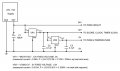
I breadboarded a circuit now with a 24V supply that delivers 24V, 12V and 5V.
I've found now using a 78T12 fixed voltage regulator (rated at 3A), the heat is considerably less.
I then tapped off the 12V a 5V supply using a 7805. This produces no heat.
Can anyone please look at my circuit below and let me know if there is any problems with it before I create the PCB.
(Drawing above amended - C2 and C3 now off ground)
What happened with the LM2575 Need some more info here. Like how far away will the 24V 15A power supply be located from your board. And is the latter power supply stabilized(regulated) Will the power supply unit you build be located far from the electronic it will be powering. And should not C2 and C3 be connected to ground?
I tried the LM2575 with the inductor. It worked well. The only problem was again it was heating up quite a bit. It was only rated at 1amp. This is why I thought I'd look at using a different 3A unit (7812). This seemed to run cooler.
Funny thing however, when I first tested the current from the four 12V circuits a I'm running, it was around 0.7A. When I tested it today with the 7812, it was only 0.22A. I'm a little confused here. Not sure what changed. Never mind.
In the scoreboard, the 4 circuits, 24V-15A supply and the power circuit are all next to each other (all take up about 1m width).
C2 & C3 - oops - yes, I drew it incorrectly. It does go to ground.
By the way across each board I have an electrolytic across Vcc and ground at the start of the circuit and some within the circuits as well. I'm wondering if there's too many. Is this a problem:
1. Temperature circuit: 100uF, 25V
2. Scores circuit: 100uF, 25V
3. Countdown timer: 100uF, 25V
4. Clock: 100uF, 35V (plus a further 2 of these in the circuit)
5. 24V supply to PWM: 100uF, 25V (plus a further 2 of these in 12V and 5V)
I would have chosen C1 to be in range of 2200uF with a 35 volt rating, and I would also have added a ceramic cap in range of 100nF in parallel with C1. As you may have seen from the regulators data sheet. You may need an input bypass capacitor. From that I remember from other data sheets. If the regulator is located more than 2 feet away from the power source. They recommend using an input bypass capacitor
Yes, in line with all the 100uF electrolytics, I do have 0.1uF ceramics - sorry I didn't note it.
If you think in the case of the voltage regulator circuits 2200uF is better - no probs, I'll change it. The regulator itself will probably be within a foot of the 24V supply.
About the other 100uF electrolytics. Does it matter having so many essentially across Vcc and Gnd (given all the circuits off this single 24V supply?
No I should not think it would be any problem with the some 100uF caps scattered around. Oh just one more thing. Regulators require some minimum current draw to function properly. Not a problem in this design. But if you had used the LM2575 for the 0.02A supply. It could have been a problem. In such cases the regulator tend to give out somewhat higher voltage than it should. The data sheet will give you information about minimum recommended current
I've just built the combined power supply circuit and pwm PCB board. I'm going to test it out in the morning - fingers crossed. If it works, then all systems go for starting the frame.
At the same time I'll also build a second PCB for each circuit. This is so if any circuit stops working for any reason, I'll have a spare I can swap with until I find the problem and fix it. Also, I've made slight modifications to the circuits - fixing mistakes. I'll post more info tomorrow or the next day.
No I should not think it would be any problem with the some 100uF caps scattered around. Oh just one more thing. Regulators require some minimum current draw to function properly. Not a problem in this design. But if you had used the LM2575 for the 0.02A supply. It could have been a problem. In such cases the regulator tend to give out somewhat higher voltage than it should. The data sheet will give you information about minimum recommended current
Generally if you are talking 20ma, then a simple 3 terminal regulator is all you need.
You need on 2200µF+ for the main power supply, as a primary filter cap. A 220µF scattered about, say 2 per PCB, is also good. The big one though is the 0.1µF, one per chip that switches.
Generally, the larger the cap, the smaller the MTBF is (Mean Time Between Failures) is. The number is still quite good though. Also, the bigger the cap, the lower frequency it is meant for. 220µF and bigger tend to eliminate ripple, the 50 Hz from the lines. The 0.1µF is for high frequencies. They eliminate the fast transients from switching, as well as high frequency oscillations.
This is what I told Chris offline, but I thought it beared repeating.
 Facebook
 Google
 GitHub
 Linkedin
") But anyway I think you can use the LM2575-5 for creating 12 volt. As long as the LM317 for 5 volt and the LM2575 share the same ground. It is nothing wrong in feeding the LM317 from the 12 volt source in order to make it run cooler. I think the 330uh 3A High Frequency Inductor / Choke L6527 may be useable. The current rating it is somewhat overkill. But if it is the one you easy can get hold on. Just use it
But anyway I think you can use the LM2575-5 for creating 12 volt. As long as the LM317 for 5 volt and the LM2575 share the same ground. It is nothing wrong in feeding the LM317 from the 12 volt source in order to make it run cooler. I think the 330uh 3A High Frequency Inductor / Choke L6527 may be useable. The current rating it is somewhat overkill. But if it is the one you easy can get hold on. Just use it