Funny. When I looked last I didn't see the any images in your post, now they're there.
The 1st circuit you have up is the count down timer - blinking dots off pin 4 of the 4027 as you noted.
The second spot I need the blinking dots is also on my clock circuit. It's a completely different circuit. It simply shows the time. It is the second image in post #336. I don't have a wiring diagram, just my PCB layout. You'll see there however there is an annotation about a setup for blinking dots, however this hasn't been setup for my digits - wrong voltage, etc.
Yes, you can share the transistor side, more than likely. Basically the side that controls the blink will be going to ground, while the PWM is on the +24VDC side (but is designated PWM Control to distinguish it). I am picking designations at random, not knowing what your current max designation is.
Like I said, I'm in the middle of drawing. You will see a 3rd image come up in a bit, and if I see something wrong after I post I will fix it on the fly. I'll bet you aren't used to people using M/S Paint as a CAD program.
M/S paint is fine. I always say that whatever software someone knows, can use efficiently and does the job is what they should use.
As for current, the digits have 5 rows of leds each with a resistor each, drawing 15mA per string, therefore 75mA per set of blinking dots.
When you show the transistor you use, can you show me the maths of how you set it up. My "guess" for the maths is:
Resistor = 12V x Hfe / (1.3 x load current)
= 12 x 100 / (1.3 x 75mA)
= 1200 / (1.3 x 0.075) = 12KΩ
(with a resistor between base about 10 x that value?
Here I'm just looking at a 2N2222 which has a Hfe of 40 - 300), so I just picked 100. No idea why it states such a wide range. Is it based on the voltage it's letting through?
Uh, I'm afraid I do this a lot cruder. The math is used to set limits, but most times I use experience to pick a value. Part of it is I like using standard parts.
If a Darlington has a gain of a 100 (low ball and figuring for saturation), and you have 38 µA going into the base-emitter. This keeps the CMOS happy. Opps, I got the input resistor wrong, so I will change it to 10KΩ on the non-inverting in a bit. If the gain were 100, and we multiply that on the input current, we get 3.8ma, too low.
Always plan for worst case, as a general rule. The design I currently have, with 100KΩ, would probably work fine. I want to eliminate the probably.
With a standard transistor in saturation I want base-emitter current to be at lease 1/10 the collector-emitter current. This is a general rule of thumb that works. I have extrapolated that to a Darlington pair for the base-emitter current to be 1/100 of the collector-emitter current.
As I said, I was calculating for a 24V power supply With a long string of LEDs you need it. If the string is shorter you can reduce the voltage.
Rather than modifying the original, I'll repost the new revision here.
Looks good. I'll try it later today. I've just ordered 10 NPN TIP112 Darlingtons (@33 cents each). Good to have some spares. These are rated at 2A.
I'm assuming I can wire this same setup to the clock as well. Should I simply replace the existing BC547 that has the 470Ω resistor hanging off it (refer to the PCB layout diagram on post #336?
Okay, I've had some time to prototype and test a working circuit. You can elminate the toggle 555 and use the second half of the 4027. You'll be able to:
Toggle clock pause using relay 5.
Force clock pause regardless of current pause state.
Force pause (or run) at power-up.
I'm not following the current discussion between you and Bill, but I assume you're both close to solving the colon blinking issue. My only two cents would be to use a MOSFET and connect the clock signal to the gate of the MOSFET.
elec_mech, thanks for the suggestion to fixing the problem. Unfortunately at this stage Bill has come up with a solution that also fixes the problem that I've implemented on my board with success. I will however try your suggested change on my breadboard to see how it works as it uses less components.
As for the blinking colons, yes I will be connecting that to the clock signal but through a Darlington rather than Mosfet. Any reason you suggested the later in preference to a Darlington?
elec_mech, thanks for the suggestion to fixing the problem. Unfortunately at this stage Bill has come up with a solution that also fixes the problem that I've implemented on my board with success. I will however try your suggested change on my breadboard to see how it works as it uses less components.
No problem, I just wanted to try it out for myself and see if it was possible. If you're happy with what you have, no sense in changing it.
As for the blinking colons, yes I will be connecting that to the clock signal but through a Darlington rather than Mosfet. Any reason you suggested the later in preference to a Darlington?
MOSFETs are voltage-driven, transistor are current-driven. There is no problem using transistors, but I like MOSFETs because they don't require drive current (which may affect other parts on the same circuit) and they don't require a base resistor to limit current. All in all, less parts (at least one) and less worry about affecting other items feeding off or supplying the drive signal.
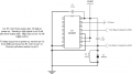
Actually MOSFETs do require a gate resistor, but for different reasons. If you are switching a MOSFET on and off, as with PWM, you are basically forcing a capacitor to charge and discharge. No problem there. Where the problem comes in is you create ringing, as resonance between the gate capacitance and the wire leading to the gate make a tuned circuit, and the MOSFET turns on and off to the AC wave form. This can cause heating and a host of other problems.
You defeat this by adding a resistor on the gate, as physically near the gate as you can get, to damp the LC circuit.
It is enough of a problem I have added an illustration to my albums. Figure a gate capacitance in neighborhood of 100pf to 0.1µF. A resistor of 0.5Ω to 10Ω usually suffices.
The other issue is you must have a low impedance drive to the MOSFET, as show by the two BJTs. Failure to do so will cause slow switching speeds (and heating). CMOS generally drives MOSFETs quite well, but they are a related technology.
Bill, thank you for the information. As always, I learn something new here almost every day.
So for simple switching applications such as ON/OFF and PWM, no gate resistor is needed? Then for AC waveforms, a gate resistor is needed? I'm a little confused as to when and when not to use a gate resistor.
Correct. If it is an occasional switch (or very slow) you can get by without a gate resistor. Usually the AC ringing is in the RF region.
You need to also remember while a gate draws almost no current (as a capacitor) it will take a largish surge current (as a capacitor charging would do). So you need not worry about heating, but design for the surge. This is actually saying the same thing I said earlier, but with a built in explanation.
If you need 2Hz, you should be able to get this by tapping off pin 3 of the 4027 or the 4060. The 4060 outputs a 2Hz signal and the 4027 is being used to half that to 1Hz.
Can you post a schematic showing how the colons are wired up? I assume you're also using the PWM signal? If yes, does the blink look right if you disconnect the PWM circuit (connect directly to Vcc/GND - whichever is correct)? Does it look right if the PWM is connected but the clock is not?
Bill,
You need to also remember while a gate draws almost no current (as a capacitor) it will take a largish surge current (as a capacitor charging would do). So you need not worry about heating, but design for the surge. This is actually saying the same thing I said earlier, but with a built in explanation.
So adding a gate resistor is a good idea for high switching frequencies and to limit surge currents? What is, roughly, the lowest frequency one needs to worry about adding a gate resistor, e.g., 100Hz, 100kHz, etc.?
Also, what affects the size of the surge current? The load current on the output side (across source and drain pins), the max current that could be applied by the circuit to the gate pin (the IC pin feeding the gate pin in this case), or something else? When is this a concern or is it just a good idea in general to use a gate resistor?
I assume there is still some benefit in using a MOSFET over a transistor since the amount of available current from a CMOS IC driving the gate is not a concern?
Show me the circuit you used, we have several floating around here. Usually you can adjust using the LED resistor. I also don't know how many LEDs in series we are talking about in series.
If you need 2Hz, you should be able to get this by tapping off pin 3 of the 4027 or the 4060. The 4060 outputs a 2Hz signal and the 4027 is being used to half that to 1Hz.
I tried that last night thinking the same thing. But pin 3 of the 4060 sends out a 2Hz signal to pin 3 of the 4027. I'm getting 1Hz at pin pin 1 of the 4027 via the flip flop setup. I'll experiment today with another 4027 on my breadboard to see if I can halve it and what it looks like when it blinks.
No, Vcc didn't produce a full brightness on the LED. I can now see the problem. Bills diagram shows a 680Ω resistor in series with the LEDs. I didn't read into this. He was simply making the diagram look correct. I already have a resistor in series for my led setup.
Bill, the colons =
7 leds in series with a 330Ω resistor
5 of these strings in parallel
Current therefore 15mA x 5 = 75mA (run on 24V, diode Vf = 2.73)
For my testing, I used a PNP darlington I found lying around. I've just looked up the datasheet now. Could someone please check it to interpret what it says:
I assume that the Hfe is referred to as the "DC current gain" in this sheet. Correct? If so, it lists it as 20min and 100max. Why 2 values?
So when calculating the current, should it be 75mA/20 = 3.2mA, or 75mA/100 = 0.75mA?
At 20Hfe, this suggests a 3.2KΩ resistor. At 100 Hfe, this ends up 16KΩ. For full saturation, should I be using the 3.2K? If so should it be a little less resistance (I read somewhere 1.3 times) = 2.5KΩ?
By trial and error, I found the brightest I could get the colon leds was with a base resistor value of around 1KΩ. Any lower the value and all the other led digits started blinking!!! Any higher the value, and the led went more dim. What value do I need?
Transistors are not precision components, their gain varies from lot to lot, and even between two identical components. This is understood by the old hands, but hard to express how bad it is. If you are using them as a switch it doesn't matter, and most circuits have negative feedback built in to cancel the problem out.
The 3055 and 2955 series are single transistors, and they were designed for high currents, not gain. They are also old. When simply switching on / off just use the 1/10 rule I mentioned earlier.
Part of the reason it exists is transistor can vary their gain depending on application! Some of the base emitter current is rerouted when the transistor is in saturation, but the 1/10 rule compensates nicely for that.
When I calculated the 680Ω I was thinking 2 LEDs, not 7, or 14. It is one reason I keep asking for schematics, in general I have some trouble keeping track of your design specs.
Sorry Bill. I will do a quick sketch. Just give me a few minutes...
Would the value of 1.6KΩ'sh be suitable? Why is it is I drop it lower than 1KΩ all the circuits go mental - start to flash?
I'm back again. Damn, I'm such an idiot. I used a TIP2955. It's a PNP not an NPN. Just changed it to a TIP3055 PNP I had - better. Even at 10K looks good. I think I need new glasses!!!
Back again... Quick video file in a zip file - didn't know how to just attach it directly. It's ony 2.8Mb. View attachment colon.zip
I think in the end 1Hz looks ok.
The whirling sound your hearing is the washing machine - sorry.
The clicking is my remote. I did the following:
1st click = F5 (pause)
2nd click = F5 (resume)
3rd click = F11 (make F9, F10 and F12 active)
4th click = F12 (load preset - goes to 40 minutes)
5th to 9th = F12 (load presets toggling through until it reaches 45:00)
10th click = F5 (resume)
Unfortunately the darlingtons I am actually going to use still haven't turned up. I buy most stuff now from "rscomponents" - relatively cheap and free overnight delivery if in stock. However occasionally it's not overnight and this week - monday was a public holiday!
Yes, I'll make a note of 1/100 for Darlingtons and 1/10 for BJTs.
You Tube - yes I was looking at doing the same - making an account. I was surprised I couldn't just attach an AVI here - as did shrink its size considerably.
Close? Yes.
I'll soon add the components to the count down timer. I'll also check I can do the same on the clock and alter it. Then I need to check out creating the 12V power supply via the LM2572 (when it comes in the post). I then have to draw up the circuit board for the combined power and PWM circuits and build it. Next...building the frame!
If all goes well, yes, I'm guessing alot of other clubs will then show some interest.
 Facebook
 Google
 GitHub
 Linkedin