Corsair PSU cs600 blowing fuse in power stabilizer

Thread Starter

Decio Souza

Joined Apr 29, 2017
6
Hi there total noon here.
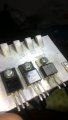
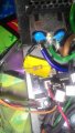
I have a corsair cs600 connected to a power stabilizer and every time I try to power it up it blows the fuse on the stabilizer, I removed this resistor and stoped blowing the fuse on the stabilizer, but then it blew the fuse on the PSU not on the stabilizer.
My questions are
Colds this resistor be in short causing the fuse on stabilizer to blow out
What is the resistance on this resistor. I can't figure it out
Could the culprit be that yellow thing(I think its a capacitor)

I thank you all in advance for any help
 

Attachments

Dodgydave

Joined Jun 22, 2012
11,285
The resistor is 1.4M to discharge the Yellow thing, a Capacitor across the mains input, and the two Blue things are mains suppression capacitors,.

What happens when you plug the psu directly into the mains supply.?
 

Thread Starter

Decio Souza

Joined Apr 29, 2017
6
The resistor is 1.4M to discharge the Yellow thing, a Capacitor across the mains input, and the two Blue things are mains suppression capacitors,.

What happens when you plug the psu directly into the mains supply.?
when i connected the PSU directly into the main power suply it blew the 9v fuse on the PSU.
I used a multimeter to test the resistor and it read 1.8m ohms, I thought it was open and causing the capacitor to short blowing the fuse on the stabilizer and I was thinking that if I change the resistor it could fix the PSU.
 

Thread Starter

Decio Souza

Joined Apr 29, 2017
6
Then you obviously have a fault on the 9v rail.
i checked the first stage on the psi with a meter in continuit mode, bridge rectifier and filter semms to be ok, follow the rail to a couple of transistors in parallel. By touching the meter to the 9v rail and the first leg on the transistors they both would beep. I removed the transsistors out of the board when touching the meter to middle leg to the side legs on the transistors there was no beep, touching the side legs with the meter no beep either. I thought the transistors where ok and put then back on the board.
I don't know if I measure the transistors right.
 

ian field

Joined Oct 27, 2012
6,536
The middle one is a Nfet, the right one is a diode, can't see the left one.
The MOSFET is a 600V type, so that must be a primary side heatsink assembly. That MOSFET is a suspect and possibly the bridge rectifier.

The description seems to hint more of a secondary side fault - more info is needed to untangle this one.

A PFC front end on the primary side would change the dynamic of the fault finding procedure.
 

Thread Starter

Decio Souza

Joined Apr 29, 2017
6
The MOSFET is a 600V type, so that must be a primary side heatsink assembly. That MOSFET is a suspect and possibly the bridge rectifier.

The description seems to hint more of a secondary side fault - more info is needed to untangle this one.

A PFC front end on the primary side would change the dynamic of the fault finding procedure.
you are right the mosfet it's located on the secondary side, o remove them from the board and tested it with DMM on the diode mode, negative lead on gate, positive on source and then on drain and got a beep, then negative lead on souce and back to gate no beep, when measuring resistance at 200k mosfet read 580ohms.
Do the test implies the mosfet it's ok and I should move to ne next component or should I replace them anyways?
 

ian field

Joined Oct 27, 2012
6,536
you are right the mosfet it's located on the secondary side, o remove them from the board and tested it with DMM on the diode mode, negative lead on gate, positive on source and then on drain and got a beep, then negative lead on souce and back to gate no beep, when measuring resistance at 200k mosfet read 580ohms.
Do the test implies the mosfet it's ok and I should move to ne next component or should I replace them anyways?
You have to be a bit careful testing MOSFETs out of circuit - you can put a charge on the gate capacitance just by touching it, that can make it conduct and give a false leaky/short reading.

You can short the gate and source while testing, but that can on rare occasions give an optimistic result. Normally I just short the G/S to discharge the gate capacitance before making the test. The MOSFET should switch off and stay off unless you accidentally put any charge on the gate.
 
Top