Facebook
 Google
 GitHub
 Linkedin
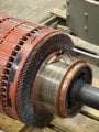
I am currently in a summer internship at a company after my first year of university. After only one year of intro level engineering classes, I do not have much experience or knowledge and blame my ignorance on that. I am currently working on updating the design and implementation of a DC Motor Armature tester that was designed nearly 50 years ago. I have a working circuit, which is (for now) powered by 2 24V power supplies, and eventually will be adapted to run off of drill batteries. The signal from the Transmitter circuit is sent through a 2-arm wand which is placed on the commutator of the tested motor and induces an AC signal into the windings. This signal is then picked up by a 2-prong receiver which measures the received voltage across two bars and reads it. If the voltage is over a certain level, there is a bar-to-bar open, if in a normal level, the bars are good, if minimal voltage is picked up, there is a bar-to-bar short. The Receiver is a separate circuit, but the op amp blows without the receiver connected, so I omitted that.
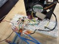
Now for the issue, my circuit seems to work fine for the most part, but occasionally, the Op Amp can blow, and I read the signal on my oscilloscope as -24VDC. I am thinking that it could be due to too much current flowing through the op amp, or possibly back emf from disconnecting the load. I am not sure if the back emf idea is plausible here, as it is an AC signal that is sent through the wand. I am wondering what the reason for the Op-amp blowing is, and any other critiques or suggestions are greatly welcomed and appreciated.
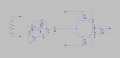
I will attach pictures of my transmitter circuit as well as the previous circuit design.
I am using an OPA445AP op amp, and TIP41C and TIP42C transistors. The "resistors" labeled Pot1 and Pot2 are two sides of the gang potentiometer I have included to adjust frequency. (Also have never posted on a forum before so excuse my mistakes)
Thanks.
Now for the issue, my circuit seems to work fine for the most part, but occasionally, the Op Amp can blow, and I read the signal on my oscilloscope as -24VDC. I am thinking that it could be due to too much current flowing through the op amp, or possibly back emf from disconnecting the load. I am not sure if the back emf idea is plausible here, as it is an AC signal that is sent through the wand. I am wondering what the reason for the Op-amp blowing is, and any other critiques or suggestions are greatly welcomed and appreciated.
I will attach pictures of my transmitter circuit as well as the previous circuit design.
I am using an OPA445AP op amp, and TIP41C and TIP42C transistors. The "resistors" labeled Pot1 and Pot2 are two sides of the gang potentiometer I have included to adjust frequency. (Also have never posted on a forum before so excuse my mistakes)
Thanks.
Attachments
-
 37 KB Views: 19
 -
4.2 MB Views: 9
-
4.8 MB Views: 3
-
5.7 MB Views: 4
-
4.7 MB Views: 2
-
4.5 MB Views: 4
-
 2.9 MB Views: 17