 Facebook
 Google
 GitHub
 Linkedin
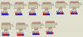
After some experiements with Proteus I found out that in A, B, C, D inputs of the 74H145 / 74HC145 the A is LSB and D is MSB because if A is taken as MSB and D as LSB and values 0x00 to 0x09 are assigned then multiple output channels will be low for some value. So, I assume this is incorrect.
I am attaching an image which shows for BCD values 0 to 9 only one output of the 74H145 will be low and LED connected to that particular channel will lit. In image the blue square at the pins represent low (0) and red square represent high (1).

I am attaching an image which shows for BCD values 0 to 9 only one output of the 74H145 will be low and LED connected to that particular channel will lit. In image the blue square at the pins represent low (0) and red square represent high (1).
Attachments
-
 42.4 KB Views: 0


