Convert this circuit to MosFETs

crutschow

Joined Mar 14, 2008
34,411
.......................
I do have a question ... Should R2 and R3 both be 10k ohms? I ask because there is a 7 volt difference to trigger the circuit.
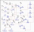
They can both be the same resistor, it just means the 12V input will have more overdrive.
You want the base current to be 1/10 or more of the collector current to fully saturate the transistor, and that is met for both inputs with 10kΩ resistors.
You can increase the 12V input resistance if you want to, but there's no compelling reason to do so, unless you want to save a few tenths of a mA of current.
 

Thread Starter

stillgrowingup

Joined Jul 15, 2015
210
Hi crutschow

I am still waiting to receive the mosfet so I may test your circuit design. I was reminded by my Aunt about one small thing that MAY be necessary. That turn indicator needs to be amber/yellow ... not clear. I still want the all 6 fog lamps to be clear. So the alternative is to place a Amber/Yellow LED within the same fog lamp housing to be illuminated as turn indicators. Not a problem.

With the proposed circuit design, I will be able to wire the turn indicator LEDs directly to the turn lamp signal. So when the foglamp circuit is activated. The 55 watt bulb will go off and the Amber/Yellow LED will come on. In theory the Fog lamp and Turn indicator LED will flip flop back and forth, making for a GREAT turn indicator. :)

But .... without the fog lamp circuit activated. Both the 55 watt lamp AND the Amber/Yellow LED turn indicator will be activated at the same time. This will not be good. :(

So I ask, is there a way to utilize the remaining part of the CD4030B to accomplish this.

Thank you crutschow for all your input.

TONY
 

crutschow

Joined Mar 14, 2008
34,411
I can add logic to suppress the flashing of the fog lamp when the fog lights are off.
To do anything else requires more complex timing circuits.
The modified circuit to do this is shown below.
It requires the addition of two more chips, a CD4049 and a CD4081.

upload_2016-8-31_10-45-38.png
 

Attachments

Last edited:

Thread Starter

stillgrowingup

Joined Jul 15, 2015
210
Thanks again!!!! The LEDs I'm using are 20mA with the 1.95v forward voltage.

This newer circuit design looks like the same exact design. Just the chips are different. Am I correct?

TONY
 

crutschow

Joined Mar 14, 2008
34,411
There is some circuitry that should be added to help protect the logic gates from the transients on the 12V line.
Add a 100kΩ resistor in series with the line from the right and left turn signals to the two gates (after the resistors to ground).
Also add a 0.1μF cap from between each of the resistors and the gates to ground.
 

Thread Starter

stillgrowingup

Joined Jul 15, 2015
210
There is some circuitry that should be added to help protect the logic gates from the transients on the 12V line.
Add a 100kΩ resistor in series with the line from the right and left turn signals to the two gates (after the resistors to ground).
Also add a 0.1μF cap from between each of the resistors and the gates to ground.
Hi Crutschow

I believe I understand your verbal instructions. My sim worked!! :) ... Please review the attachment to confirm I truly understand. :)

TONY
 

Attachments

crutschow

Joined Mar 14, 2008
34,411
Not quite.
C2 and C3 should be at the junction of the resistor and the input to gates U1-A and U1-B.
That way you have a low-pass filter at the gate's inputs to absorb any high frequency spikes.
 

Thread Starter

stillgrowingup

Joined Jul 15, 2015
210
Not quite.
C2 and C3 should be at the junction of the resistor and the input to gates U1-A and U1-B.
That way you have a low-pass filter at the gate's inputs to absorb any high frequency spikes.
Thank you for noticing my error and explaining why it is needed. Very helpful. I have uploaded the correction circuit.

Will a 1/4 watt resistor be sufficient?

Thanks
TONY
 

Attachments

Last edited:
Top