Convert this circuit to MosFETs

Thread Starter

stillgrowingup

Joined Jul 15, 2015
210
Hi All,

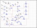
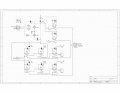
I have a working circuit that uses relays for the heavy lifting. (See Attachment) But I would like to use mosfets instead. I have NEVER dealt with mosfets before and do NOT know where to start in choosing the correct mosfet to replace the relays.

Here is what the circuit does ... I have 6 driving lights in front of my car. I would like the outer lamps to respond as turn signals (turn indicators). Each lamp is a 55 watt halogen bulb that draws 4.8 Amps each. I will be putting this in a project box and would like to NOT use heat sink with the mosfets (if possible). Can you guys please help?

Thanks
TONY
 

Attachments

ScottWang

Joined Aug 23, 2012
7,409
Vcc = 12V
I_bulb = 4.8A
W_bulb = 57.6W

So choosing the Vds ≥ 12V*2, Vgs=± 20V, Ids ≥ 4.8A*3, Rds(sat) ≤ 10mΩ, choosing the Rds(sat) as much small as you can.

Since you don't want to use the heat sink, if using the small heat sink as shown in the below picture, or maybe smaller, is that ok for you?


Two 4 kinds ±5~15V fixed power as ±5V, ±9V, ±12V, ±15V

The following circuit can be replace the npn bjt+relay.
R1 as labeled, R2 = 10K~22K,
The pin of Sw1 and R1 is the input.
NmosfetTestingCircuit-ScottWang-01.gif

The following circuit can be replace the pnp bjt+relay.
R1 = 10K~22K, R2 as labeled.
The pin of Sw1 and R2 is the input.
PmosfetTestingCircuit-ScottWang-01.gif

You can choosing the mosfet from digikey or mouser or some other ee components that you knew.
 

Thread Starter

stillgrowingup

Joined Jul 15, 2015
210
Hi Scott! :)

I would like NO heat sink.

Some of the relays in my design use both N.C. and N.O. contact on one relay. Is there a mosfet that can do that? I have looked but not found a mosfet with that feature.

Tony
 

Thread Starter

stillgrowingup

Joined Jul 15, 2015
210
HI Scott ... Thank you for the N.C and N.O. mosfet circuits. Looks like your N.C/N.O. above diagram switches ground. I need to switch the power .... I am starting to believe converting this circuit from relays to Mosfets is NOT worth the trouble. The reason I say this is ... after looking, I do NOT think a mosfet will work WITHOUT heatsink :( ... and ... the overall footprint of components needed for a mosfet circuit (with heatsinks) is bigger than my original relay circuit.

What are your thoughts? ... And any ones elses thoughts. :)

TONY
 

crutschow

Joined Mar 14, 2008
34,470
Could you explain exactly what you want the circuit to do, in other words what outputs for what inputs?
What do the "5V Trigger In", "12V Trigger In", "Ground Out When Active" and "Ground Trigger In" do?
The circuit seems overly complicated for what it apparently does.

Yes, you can find MOSFETs that don't require heatsinks, they just have to have a low enough ON resistance to keep the dissipation below about a watt when conducting.
For your load of 4.8A this means the MOSFET ON resistance should be less than 1/4.8² = 0.04Ω and those are readily available.
 

ScottWang

Joined Aug 23, 2012
7,409
The power dissipation is:
W = V * I
Wds = Vds * Ids
Vds = Ids * Rds(sat)

TwoPmosfetsToReplaceRelayAndBjt-circuit-ScottWang.gif

If you could describe some more details as crutschow asked, maybe N mosfet still can do the job, otherwise you have to using the P type mosfet.

The Rds(sat) of attached file was pretty low as 2.5mΩ, so the Wds also to be low, and maybe you don't need to using the heat sink.
 

Attachments

Thread Starter

stillgrowingup

Joined Jul 15, 2015
210
Could you explain exactly what you want the circuit to do, in other words what outputs for what inputs?
What do the "5V Trigger In", "12V Trigger In", "Ground Out When Active" and "Ground Trigger In" do?
The circuit seems overly complicated for what it apparently does.
Hi Crutschow,

I have 6 front facing fog lights (Driving Lamps) on my car. From Left to Right while standing in front of the car, I'll number them 1 - 6 for the sake explaining more clearly what I am after.

I need for ALL 6 fog light to come on at the same time by any one of 3 inputs:
5V IN - for a Latching signal from my arduino.
12V IN - for the stock OEM fog light switch.
Ground IN - for a latching output from my car alarm.
Ground OUT when Active - to illuminate a 1 watt indicator bulb inside the car.

Right Turn/Left Turn 12v Input - When the turn signal lever is depressed by the driver (me) to indicate my desired movement. The OEM electrical system sends a 12v pulsing output (through a flasher relay) directly to the incandescent bulb.

With these signals, I need the outer Fog Lamps (Far left and Far right) to not only be used as a fog lamps ... BUT also as turn indicators. With the Fog lamps off (Daytime driving) the outer lamps flash ON, then OFF for the duration the Turn lever is depressed inside the car. Allowing the OUTER fog lamps to indicate I am making a turn. BUT ... with the fog lights ON (night time driving). I need the Outer fog lamps to turn OFF, then ON to indicate I am making a turn. The circuit I made with relays in post #1 does accomplish this very well.

The middle fog lamps (2 through 5) work as standard fog lamps. Off during the day, On at night. You will see I have 2 relays (K7 and K8) to operate the middle 4 fog lamps. The relays I use have a max current rating of 15A. I have 2 of these 55W (4.8 Amp) incandescent foglamps per relay so I do not cause the relays to fail.

Because overall size is an issue and I will probably be mounting this under the hood. I am thinking I should use Mosfets instead of relays. But I have NO experience with Mosfets. I know Mosfets can get hot .... LOL :) ... thats way I am concerned about possible heat building up inside a plastic project box.

The Rds(sat) of attached file was pretty low as 2.5mΩ, so the Wds also to be low, and maybe you don't need to using the heat sink.
Thanks for finding that mosfet. I hope I explained things well above.

TONY
 

crutschow

Joined Mar 14, 2008
34,470
What does the "Ground IN - for a latching output from my car alarm" do?

Note that automotive relay coils typically dissipate over a watt when on, so a good MOSFET should dissipate less than that.
 

Thread Starter

stillgrowingup

Joined Jul 15, 2015
210
What does the "Ground IN - for a latching output from my car alarm" do?
My car alarm/security unit sends out a latching/toggled 300mA ground output when triggered. ... this will allow me to activate the fog lamps by pushing a button on my alarm/security keychain fob.

Tony
 

crutschow

Joined Mar 14, 2008
34,470
So here's my take on a fairly simple circuit that, I think, does what you want.
It uses P-MOSFETs as switches, with two CMOS XOR gates for the logic to flash the one running light from the turn signal whether the running lights are on or off.
The MOSFETs are IPP120P04P4L-03 which is a low cost, low ON resistance device.
I used two for the running lights, even though one would have been sufficient, for less stress and power dissipation in each transistor.
The maximum dissipation is about 0.4 watt per transistor when ON so the heat build-up will be much less than with all the relays you had.
The RLD resistors simulate the bulb loads and aren't part of the circuit.
The NPN can be the BD139 you used (I didn't have it in my model library).
I don't show any fuses. You can put those in as you see fit.
The simulation shows the output bulb currents for various combinations of inputs.

Note that the unused inputs (not outputs) of the CD4030 must be connected to ground.
Do not leave them floating.

upload_2016-8-22_22-41-15.png
 

Attachments

Last edited:

Thread Starter

stillgrowingup

Joined Jul 15, 2015
210
So here's my take on a fairly simple circuit that, I think, does what you want.
Crutschow

I ran your circuit on my simulator and YES!!!! It does seem to do what I need. :) Thank you SO MUCH!!!! ... I will order the parts needed so I may do a breadboard test. I added a couple of status LEDs in the circuit as well.

I have attached my simulated circuit. I didn't have the correct Mosfets you recommended or 55w bulbs in my simulator. But the circuit still worked. THANK YOU ... I will report my finding when the Bread board test is done. ... approx 1 week. :)

TONY
 

Attachments

crutschow

Joined Mar 14, 2008
34,470
Looks okay except the CD4030 cannot reliably sink the 10mA or so through the LED that the 1kΩ series resistor will cause. :eek:
If you look at the output voltage of the CD4030 when the LED is ON, you will likely see that it is a volt or more, which is too high (my LTspice simulation shows about 1.5V).
Your sim may give a lower voltage since you show a 15V model but I can set mine to 12V.

The gate is limited to worst-case sinking no more than about 3mA, as estimated at a Vdd of 12V (from here, page 3-91).
You need to increase the resistor in series with the LED to around 3kΩ (my sim gives about a 0.6V output for that -- much better).
That should still give you a sufficiently bright light, especially if you use high brightness type LEDs.
 
Last edited:

Thread Starter

stillgrowingup

Joined Jul 15, 2015
210
Looks okay except the CD4030 cannot reliably sink the 10mA or so through the LED that the 1kΩ series resistor will cause. :eek:
(That's why you can't completely trust simulator results. They generally don't show worst-case).
It's limited to sinking no more than about 3mA, as estimated at a Vdd of 12V (from here, page 3-91).
You need to increase the resistor in series with the LED to around 3kΩ.
That should still give you a sufficiently bright light, especially if you use high brightness type LEDs.
Thanks again ... I typically use 2k resistors with these LEDs I have. But for some reason ... the simulation wouldn't work with 2k, so I inputed 1k to make the sim work. Like you said, simulations don't always work. :) .. I'll increase to 3k on the breadboard when i get the mosfets in.

TONY
 

crutschow

Joined Mar 14, 2008
34,470
Something else occurred to me.
You should connect the LED resistors to the filtered +12V where R1 is connected, to minimize any high voltage spikes on the raw 12V that could damage the CD4030 inputs.
Also the CD4030 power should be from that filter output.

Edit: Just noticed that you grounded the outputs of the unused gates.
That probably won't do any harm, since the outputs will be zero, but it's better to leave them open.
The general rule for CMOS is tie down all unused inputs but leave the outputs open.
 
Last edited:

cmartinez

Joined Jan 17, 2007
8,257
You stated the same thing in post #13. I just didn't pay attention. Sorry :( .... and Thank you.

I have updated the circuit and attached it to this post.

TONY
The outputs of U1C and U1D are better left floating, as you've already shown in your diagram. But I strongly suggest you ground their inputs, or the chip's gonna start doing some pretty strange things later on.
 
Top