Convert TDA2030 Amplifier Module Push/Pull Output to "Class A"

Thread Starter

Sir Kit

Joined Feb 29, 2012
188
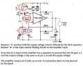
I have a audio amplifier module with push/pull output via a TDA2030. It operates from single rail 12VDC supply. I would like to convert the output signal to a class A type effect. In other words, so there is no current reversal relative to signal ground, and it idles at around half of the single supply rail. What would be the simplest way to do this external to the module?
 

LesJones

Joined Jan 8, 2017
4,174
Class A has nothing to do with with split or single ended power supplies. It is related to the quiescent current of the output devices. Read this description of amplifier operating modes. It would not be possible to modify a TDA2030 to run in class A. What you seem to be describing seems to be your existing single rail design but with the output DC blocking capacitor removed. A description of what you are trying to achieve would help us to understand exactly what you require.

Les.
 

Audioguru again

Joined Oct 21, 2019
6,671
The TDA2030 and TDA2030A are both obsolete.
The TDA2030 was designed to use a 28V supply, the TDA2030A was designed for a 36V supply. A graph on the TDA2030 shows a 16V supply but does not show 12V and extending the graph down to 12V shows an output of less than 1W into 8 ohms or about 1.5W into 4 ohms.

What is a "class-A effect"? Producing lots of heat even with no signal?
What is "no current reversal relative to signal ground"? The original class-AB output coupling capacitor reverses current in the speaker smoothly the same as the output coupling capacitor does on class-A.

To make the TDA2030 into a class-A amplifier you simply add a high power 2 ohm or 4 ohm resistor to ground or to the positive supply at the IC output but before the output coupling capacitor, then the added resistor and the TDA2030A will both get very hot all the time and the maximum audio output will be much less than the original class-AB.

The first page of the datasheet shows three 100k resistors and one 22uF capacitor biasing pin 1 input at half the supply voltage causing the output to also be at half the supply voltage like most amplifiers. Then of course it has an output coupling capacitor to pass the audio but block the DC.
 

Thread Starter

Sir Kit

Joined Feb 29, 2012
188
To clarify, I would like the "off" voltage to sit midway with respect to the output amplitude. In other words, no crossover as in a type A amp. The reason is so current to the load is unipolar or does not reverse across the load.
 

Thread Starter

Sir Kit

Joined Feb 29, 2012
188
I am aware of the limitations of the TDA2030, which being an old guy I just happen to have in my shed in the form of pre-built modules. 12VDC supply is sufficient for my application.

As I understand, the purpose of the suggested 2 or 4 ohm resistor is to pull the output up relative to ground. This would cause the output to sit at about half rail of the single supply at "zero" signal voltage. Current would thus continuously flow at half the amp's designed wattage making a nice heater. Vpp out would be reduced by half.

Rather than do that, I would like to know how the datasheet circuit you refer to (see below) can be modified so the amp's output current to the load does not reverse. The input signal is from a computer headphone socket so it is also push/pull. Thanks for any advice you can offer.

tda2030.png
 

LesJones

Joined Jan 8, 2017
4,174
AG's suggestion of adding the resistor would convert it to class A (I had not thought of that way to convert it to a single ended class A. I was thinking in terms of increasing the quiescent current of the output stage to make it push pull class A when I said it was not possible.) Adding the resistor would not change the DC level on the output pin. (Pin 4) I do not understand why you do not want the output current to reverse. Can you explain the reason ?

Les.
 

crutschow

Joined Mar 14, 2008
34,280
For experimental purposes, I am driving magnetic coils at audio frequency and want the field to not reverse.
Then, after the output capacitor, add a diode in series with the coil (cathode to coil) and a diode to ground (anode to ground).
 
Last edited:

Thread Starter

Sir Kit

Joined Feb 29, 2012
188
Then, after the output capacitor, add a diode in series with the coil (cathode to coil) and a diode to ground (anode to ground).
If I am correct, it seems you are suggesting to half-wave rectify the outptu signal. But I would prefer to retain the original wave form intact.
 

dendad

Joined Feb 20, 2016
4,451
I do not see why you need the output at half rail volts. As the circuit is drawn, the output is at half rail volts.
If you drive the TDA2030 pin 1 with a DC signal, and connect the coil from the output to gnd, it will only have the current flowing one way. Just remove the output coupling capacitor. But, limit the current to a safe value, so a series resistor may be needed, depending on you coil resistance.
I expect smoke ;)

I think you need a servo amp.
Or an adjustable current source. Not an audio amp.
 

crutschow

Joined Mar 14, 2008
34,280
In other words, so there is no current reversal relative to signal ground, and it idles at around half of the single supply rail. What would be the simplest way to do this external to the module?
Okay.
Just connect the load to ground and eliminate the output capacitor as dendad suggested.
The lower half of the push-pull output will then essentially do nothing.

What is your coil resistance and inductance?
What frequency range?
 

LesJones

Joined Jan 8, 2017
4,174
Hi crutschow,
I think with that method that the capacitor would just charge the capacitor up to the peak value of the waveform after a few cycles of the waveform. I think the diode method would work with the diode between ground and the output side of the capacitor. If the cathode of the diode was connected to the capacitor output then te output of the capacitor would swing from about -0.7 volts to + the peak to peak voltage minus about 0.7 volts.
I think this method was used was used after passing video signals through a capacitor coupled amplifier so that the negative of the video signal was at about ground level. I think it was called a DC restorer.

Les.
 
Last edited:

Audioguru again

Joined Oct 21, 2019
6,671
Since you have a solenoid instead pf a speaker and you want the DC in it, then remove the output coupling capacitor from the biased amplifier and the input signal will cause the current in the solenoid to increase and decrease. The amplifier will operate in class-A and the coil and the amplifier will get very hot all the time.
 

Attachments

Thread Starter

Sir Kit

Joined Feb 29, 2012
188
I do not see why you need the output at half rail volts. As the circuit is drawn, the output is at half rail volts.
If you drive the TDA2030 pin 1 with a DC signal, and connect the coil from the output to gnd, it will only have the current flowing one way. Just remove the output coupling capacitor. But, limit the current to a safe value, so a series resistor may be needed, depending on you coil resistance.
As mentioned, the amp input is push/pull. I believe the circuit as drawn in the data sheet will apply bidirectional current to the load. I would like it to be unidirectional.

A few solutions have now been suggested. Input DC level adjust, remove output decoupling cap or add diodes. If I am correct, it seems the latter may be the tidiest approach.

I removed the decoupling caps from a USB sound card once so as to pass subaudio frequencies. I then had to heatsink the tiny chip due to prevent overheating. Couldn't fit in back in the case.
 
Last edited:

Thread Starter

Sir Kit

Joined Feb 29, 2012
188
Okay.
Just connect the load to ground and eliminate the output capacitor as dendad suggested.
The lower half of the push-pull output will then essentially do nothing.

What is your coil resistance and inductance?
What frequency range?
By "do nothing" I would think the lower part of the wave form goes missing. Coils are wide area loops. Air core. Negligible resistance. I would use a series connected load resistor to ground.
 

dendad

Joined Feb 20, 2016
4,451
If you remove the output cap, the current will be unidirectional, that is, if you are running the amp on a single supply. Not a +/- pair.
In the circuit I posted, #13, the trim pot feeding DC bias to pin 1 can set the standing current by adjusting the DC steady state on the output. That may be helpful, otherswise just leave the pair of 100K resistors as is.
You will need the coil to have enough resistance to limit the max current to less that 3.5Amps. Also, heatsinging the amp will be needed as it will get hot.
 

crutschow

Joined Mar 14, 2008
34,280
By "do nothing" I would think the lower part of the wave form goes missing.
No.
By "do nothing" I meant the bottom half of the push-pull output would not be active, and the top half would act as a Class A amp.
So the output will go from the max voltage, as determined by the supply voltage, to near ground.
You would not miss the bottom half of the waveform.
 

Thread Starter

Sir Kit

Joined Feb 29, 2012
188
No.
By "do nothing" I meant the bottom half of the push-pull output would not be active, and the top half would act as a Class A amp.
So the output will go from the max voltage, as determined by the supply voltage, to near ground.
You would not miss the bottom half of the waveform.
OK. I should have picked that up. The output wave form would be intact, but at only half the amplitude achieved with push/pull.

Just one more thing please, how does this affect the current consumed by the amp? Can I lower the load resistance to compensate for loss of power due to the decreased signal amplitude?

I will try the recommendations so far. Time to hit the workbench.
 
Top