Convert old Analog Ammeter to voltmeter? ..#2

Thread Starter

Tom L.

Joined Feb 3, 2015
9
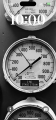
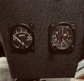
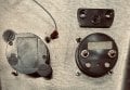
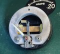
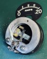
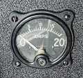
I hope I can get some help converting this amp meter to a volt meter. It is a very nice military meter that I would like to go along side an 8-day clock from my military days, both are in my restored car I had then, 55 years ago. My electronics training was so long ago I have forgotten much. There are two terminals on the back, no external shunt. I can take it apart, I have not done that, only to separate it from the case. Thanks in advance. Tom L.

Mod: link to old thread.
https://forum.allaboutcircuits.com/...nalog-ammeter-to-voltmeter.109867/post-847445
 

Attachments

LesJones

Joined Jan 8, 2017
4,511
There will be a current shunt across the meter terminals. this wil probably be a strip of metal to act as a very low value resistor. this may be on the inside of the meter. If it does not have a shunt it may have been used with an external shunt remote from the meter. To use it as a volt meter the shunt must be removed and a suitable value resistor must be connected in series with the meter. The basic meter will probably require a few miliamps for full scale deflection. ( Between 0.1 mA and 5 mA.) Start with say a 12K resistor in series with the meter and a 12 volt supply. Try reversing the polarity if the needle does not move. If the meter reads full scale then try a higher value resistor. Report the results.

Les.
 

MisterBill2

Joined Jan 23, 2018
27,319
My very first step is to ask questions: Is that meter presently connected and functioning as an ammeter? If that is the case, the next question will be about the wiring of the meter as it is, if it is currently serving as an ammeter.
I have observed that there are three possible arrangements with panel mounted ammeters:
First is with an external shunt resistor that the current passes thru and develops a small voltage, possibly up to one hundred millivolts, and the meter directly reading that voltage and displaying the voltage to show the current.
The second arrangement is for the similar shunt resistance to be located within the meter package, either externally, on the terminals outside, or internally, within the meter case. In this case the meter will also be functioning as a voltmeter to read the shunt voltage and display that as "AMPS". This arrangement will be obvious because the meter connection wires will be heavier, since they will carry the full current.
The third arrangement is rather different, which is in an antique "Weston" meter package I have. In this case the meter itself is a different scheme, with an internal high-current coil that the measured current passes through, rather than a shunt resistor. In this arrangement also the external leads to the meter will be heavy wire that carry the full current being measured. For this arrangement the meter is directly measuring current, rather than voltage.
If this is the type of meter movement, a conversion to display voltage will not be simple at all.
The first two arrangements will simply require a suitable series resistor as L.J. described in post #2.
 

MrChips

Joined Oct 2, 2009
34,700
Two things you can do.

1) Examine the meter movement very closely from the front window. If you can see a coil on an aluminum frame then you can move on to the next step.

1748441677970.png

2) Open the back of the meter and look for a shunt inside the meter.
 

Ramussons

Joined May 3, 2013
1,567
Those days, there were may ammeters that did not have a shunt. They used a Moving Iron mechanism and the coil had a few turns and carried the full current.
Such meters cannot be converted to a Voltmeter.
Study the construction. If the coil is made of thick wire with just a couple of turns, then this cannot be converted to a voltmeter.
 

schmitt trigger

Joined Jul 12, 2010
2,056
What a beautiful meter! I can understand your desire to use it. I love vintage meters, as you can guess from my avatar ;)
Ramusson’s advice is a good one. If the coil which moves the needle is made of thick wire then it can’t be used as a voltmeter.
But you can still use it, to measure the actual current coming out from the generator.
 

MrChips

Joined Oct 2, 2009
34,700
I thing a more viable solution would be to replace the meter internals with a modern meter movement, i.e. just reuse the meter housing. You can easily fabricate a new meter scale.
 

Thread Starter

Tom L.

Joined Feb 3, 2015
9
Thank you all for your thoughtful and timely responses!!! I do appreciate it so very much. I may not have the opportunity to open the meter until late tonight or late tomorrow but I will report my findings as soon as I can. I was Air Force from '68-'72, worked on a variety of aircraft, some older, some state of the art namely U-2's, drones. Avionics specialist, but changed career paths in '72 so much of my training is hidden in the depths of my brain! For what it is worth, here is the meter in the panel next to my "8-day" wind up aircraft clock. The back side of the meter, (right side) has heavy lugs. The plastic piece was over the lugs, just plastic, nothing inside. Thanks again. Tom L
 

Attachments

MrChips

Joined Oct 2, 2009
34,700
Your Weston Model 606 is most likely a moving iron ammeter.
Vintage panel meters are readily available. I have a few similar to that. You would be better to leave that one as is and search for a meter movement at better suits your requirements.
 

LesJones

Joined Jan 8, 2017
4,511
I don't think it is a moving iron meter as the scale on them was not linear. The meter in the picture is quite a linear scale o I think it will be a moving coil meter. (Like the illustration in post #4 )
Les.
 

MisterBill2

Joined Jan 23, 2018
27,319
Most meters had heavy posts, for many years that was a standard no matter if it was one milliamp full scale or 500 MA FS. Not sure about the reason, but even my one V.U. meter had those heavy posts.
 

MisterBill2

Joined Jan 23, 2018
27,319
OK, the pictures show a shunt resistor and a series resistor, so this is a standard configuration with an internal shunt and a calibration resistor. So it can be made into a voltmeter by removing the shunt and adding a high resistance series resistor.
BUT extreme caution is needed because that moving coil is very fine wire, easy to damage and probably not possible to repair or replace. To start with a series resistor value, select a series resistor that will allow one milliamp of current with 20 volts applied. You will need a DC power source that can be set to one volt. See what deflection one volt with the 20K series resistor provides. IF the meter has a one milliamp movement the meter would indicate a bit less than one volt.
 

Thread Starter

Tom L.

Joined Feb 3, 2015
9
Thank you very much! I have had just a few minutes tonight to take a better look at the meter internals and I see that that internal shunt is soldered to the terminals and I don't see a way right now to remove it without dis-assembling the coil/pointer to clear the frame. However, there is a thin connector from the inside right inside terminal to the tiny nut at the bottom right of the coil mount. I should be able to dis-connect that, thereby negating the shunt/right terminal and connect a wire to that small nut/stud to act as the second terminal to test the function as a voltmeter. I do have a pot adjusted to 20k that I can connect to the left terminal exterior, to use as a trial. I will let you know when I give that a try. Thanks again! Tom L.
 
Top