Convert cordless screwdriver switch from sliding to press type.

Thread Starter

JoeCK

Joined Mar 20, 2020
62
Hello Guys,

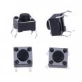
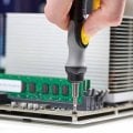
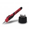
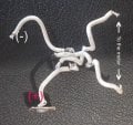
I would like to convert the cordless screwdriver switch from sliding to press type.

The sliding-type switch is a bit difficult in precision screwdriving use. So I need it into a press button switch.

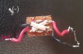
And tried it, following the actual switch wiring layout. But the problem is; the battery connectors are always short and showing continuity.

Pls find the attached pictures for the wiring I have followed and it's not working!!!

Kindly anyone can show me where is it getting messed :)

Thank you.
 

Attachments

Last edited:

SamR

Joined Mar 19, 2019
5,040
Have you tried testing the switch action with your multimeter for continuity? The buttons are turned 90° from how they are typically mounted. Test their action before mounting! Why 2 pushbuttons? That, to me, is a problem.
 

Thread Starter

JoeCK

Joined Mar 20, 2020
62
Have you tried testing the switch action with your multimeter for continuity? The buttons are turned 90° from how they are typically mounted. Test their action before mounting! Why 2 pushbuttons? That, to me, is a problem.
Thanks for the reply.

When checked, one pair of legs are always in contact, and the other pair of legs contacts when pressed.

How to solder them in this case pls? And hand drawing would be helpful and says it all :)

Thanks
 

Attachments

SamR

Joined Mar 19, 2019
5,040
What you have is actually a dual switch with one end of the 2 switches shorted. The legs are supposed to be in line with the current flow. Confusing ain't it?

1675270444620.png

This is how you have it installed...
1675270880517.png

As I've already suggested (and for any unknown circuit) use your multimeter to check continuity and sketch it out. I would also say check the PDF but these are pretty mainstream devices and all built the same but the PDF will define the switch rating if you can find their PDF. They are typically for logic level (5VDC or less) devices which may also be a problem depending on the voltage and current applied.
 

Thread Starter

JoeCK

Joined Mar 20, 2020
62
What you have is actually a dual switch with one end of the 2 switches shorted. The legs are supposed to be in line with the current flow. Confusing ain't it?

View attachment 286579

This is how you have it installed...
View attachment 286580

As I've already suggested (and for any unknown circuit) use your multimeter to check continuity and sketch it out. I would also say check the PDF but these are pretty mainstream devices and all built the same but the PDF will define the switch rating if you can find their PDF. They are typically for logic level (5VDC or less) devices which may also be a problem depending on the voltage and current applied.
Thanks for the images.

1. Can you show me how the drawing comes with two switches in the circuit?

2. They are typically for logic level (5VDC or less) devices which may also be a problem depending on the voltage and current applied:- I'm using 2 AAA batteries to power the screwdriver.
 

SamR

Joined Mar 19, 2019
5,040
1. Can you show me how the drawing comes with two switches in the circuit?

2. They are typically for logic level (5VDC or less) devices which may also be a problem depending on the voltage and current applied:- I'm using 2 AAA batteries to power the screwdriver.
1. Each switch has 2 pushbutton internal switches (redundant) which are also internally jumpered in order that if one switch fails to make contact and the other does it will operate. I don't like those switches as they rarely stay plugged into the breadboard. These are some of what I use for PBs.
1675274888964.png
The first one is kind of hard to see but is a 3 terminal PB for NO or NC with a good AC amp rating but no DC amp rating (still good for low voltage DC). Soldered to a bit of header to hold it in place on the breadboard. Second is what I typically use for a PB. Simple NO PB with some nice supple long legs that stay inserted into a breadboard that can be shrink tubed if needed. Third is for size comparison. Don't remember where I found the second but bought a lot of 50 cheap so I won't be running out forever. Well worth it at any price to avoid the problems with #3 popping off the breadboard and having to search for it.

2. With 3VDC from a pair of AAA I don't think you should have a problem with that button once it is wired correctly. Once again, why 2 of them? KISS (keep it simple stupid) actually works...
 

Tonyr1084

Joined Sep 24, 2015
7,899
Obviously the slide switch facilitates forward and reverse driving of the screw. As Sam suggested, having two buttons "Can" become a problem. What happens if you push both buttons at the same time? If wired one way I can see it shorting the motor. Wired another way it could short the battery. And shorting the battery can be a problem.

Rather than making your own momentary forward/reverse button try to find one. Just out of curiosity I'm going to look and see if such a thing exists. More likely you'll want a spring loaded rocker switch, DPDT with center off

Here's one. But it's likely going to be a lot larger than would be convenient for use. And you may be spending almost as much on a switch as you did on the screwdriver. Finding a small enough switch in a rocker form, momentary, center off - will take some searching on your part. But I would stay away from two buttons.
 

SamR

Joined Mar 19, 2019
5,040
@Tonyr1084 good catch Tony! I didn't think of the reverse. Yup, it needs 2 buttons and, YES, they should be SPDT rocker switches. Which are typically huge panel devices. These are smaller than the ones Tony linked to but still way too big. Classed mini when what you want would be a "micro"...
1675280824961.png
 

LesJones

Joined Jan 8, 2017
4,188
Two push buttons with changeover contacts (Single pole double throw.) would do what is required. Pressing both buttons at the same time would not short out the supply.
Connect the NO contacts together and to the battery positive.
Connect the NC contacts together and to the battery negative.
Connect the common of each switch to one side of the motor.
I have only seen the small switches shown in post #5 as singe pole single throw versions with normally open contacts.

Les.
 

SamR

Joined Mar 19, 2019
5,040
He may have wired it correctly the first time except the switches are rotated 90° which fouled up the wiring connections.
 

MisterBill2

Joined Jan 23, 2018
18,463
It is not at all likely that any switch able to handle the current will be small enough to fit anyplace close to the original. So if the operation really demands a powered screwdriver for some sort of precise work, one way would be to add s single pole on/off button IN ADDITION to the direction control switch, except that the direction switch is probably a spring return switch.
So another option is to use a single button, single pole switch and only run the driver in one direction.

One more thing is that all of the tiny push button switches I have seen that look like those on posts 6 and 8 are single pole with two pins connected to each side of that single switch. Use your ohm meter to verify that Four pins are there because they provide stable mounting, that is all.
 
Last edited:

panic mode

Joined Oct 10, 2011
2,740
first of all what is the current rating of original switch. the tiny push buttons are meant to work at very low currents and at low voltages. that is ok for providing an input to an MCU but not ok for powering motor.
 

LesJones

Joined Jan 8, 2017
4,188
These miniature micro switches would probably electrically meet your requirements. They are only rated a 1 amp which would not be enough for a normal electric screwdriver but as you say that your electric screwdriver is powered by two AAA cells they would not be able to supply 1 amp for long. You have not given any information on the physical size of your screwdriver so I don;t know if they are small enough.

Les.
 

Thread Starter

JoeCK

Joined Mar 20, 2020
62
Hello guys, Thanks a lot for your input.
The reason I was trying to modify the switch is;
It is for a precision screwdriver so if the on/off mechanism is not precisely controlled, the chances are high that, either we end up with a rounded screw head or tear the threads off. Pls find the image of the screwdriver below. The best I like in this is not complicated and easy to repair if gone bad.

1. At the moment the switch action is very tight and needs to apply more force.
2. The switch sliding motion on the tool is, to slide upward for loosening or slide downward for tightening.

From the replies, I understand the right-sized switch is the key. like in the last image attached (red colour screwdriver) If anyone finds it pls add the link here :)
So, for the time being, go with the same switching mechanism but with a small modification.

I have managed to find same dimension "spring that operates the switch knob in a push-pull manner" but with much less tension. now only need to apply light pressure to move the knob.

You guys are super helpful. Thanks again.
 

Attachments

Last edited:

MisterBill2

Joined Jan 23, 2018
18,463
Based on the image in post #16, I suggest to forget the powered driver and use a torque-limited manual screwdriver, and a careful operator.
There are adjustable torque drivers available that have load-cell feedback and are quite accurate and very repeatable, although they sell for a few thousand dollars. But depending on the location that might be a lot cheaper than a skilled and careful operator.
 

SamR

Joined Mar 19, 2019
5,040
I had one of those screwdrivers (the first "General" one). It didn't last very long and disassembling it to find the problem showed they are very poorly constructed, especially in the switch area where it connects with the batteries. I bought a better one... I prefer to manually break a screw loose (or seat one) and then use the powered driver to completely remove it (or start a screw). One of the reasons it rounds off Phillps head screws is the bit doesn't fit screw very well. It's a toss-up between bad bit and poorly made screw head.
 

MisterBill2

Joined Jan 23, 2018
18,463
I had one of those screwdrivers (the first "General" one). It didn't last very long and disassembling it to find the problem showed they are very poorly constructed, especially in the switch area where it connects with the batteries. I bought a better one... I prefer to manually break a screw loose (or seat one) and then use the powered driver to completely remove it (or start a screw). One of the reasons it rounds off Phillps head screws is the bit doesn't fit screw very well. It's a toss-up between bad bit and poorly made screw head.
Phillips/Reed&Pierce/and one other kind: They look similar but they take different driver bits that do not interchange very well. And the cheap bits do wear very quickly. THAT is the other reason that I suugst an industrial production qualified power driver with a reote supply and a torque sensor system.
Also, based on the picture, avoid plated brass screws. they are fragile.
 

Thread Starter

JoeCK

Joined Mar 20, 2020
62
Hello Guys,

There is an update! I just found something that works!
Hope would be helpful for someone who's looking for the solution I was searching for in this forum.

Using a motor driver chip (TA6586) and wire it according to the video below;
DC Motor Direction Changer IC Simple Circuit

Thanks again to all of you guys for your input.
 
Last edited:
Top