Controlling passive buzzer

JohnInTX

Joined Jun 26, 2012
4,787
Do I need ADC chip that will convert analog signals into digital signals. I have one MCP3008
NO. You need to go back to the original problem - buzzer not following the sensor input - and fix that.

I have never known JohnInTX to be wrong before, but maybe today is a first.
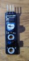
Oh, I've been wrong lots but in this case, the linked datasheet for the KY-033 sensor TS is now using shows it as having an analog output..
https://tkkrlab.nl/wiki/Arduino_KY-033_Hunt_sensor_module
 

hexreader

Joined Apr 16, 2011
619
From your link:

"Analog magnetic sensor module and a digital interface "

Example code seems to be handling digital.

Pity there is no schematic available to be certain

@OP
Please would you post clear pictures of front and back of the module.
Please read and report on the numbers written on top of the 8-pin chip.
Maybe I can construct schematic from pictures - (maybe not)
 
Last edited:

Thread Starter

Djsarakar

Joined Jul 26, 2020
489
Hexreader's codes are working. I understood here that when the sensor is not active , the led should be off for a 1 seconds

I was not giving time for the LED to go off when the sensor is not active.
 

JohnInTX

Joined Jun 26, 2012
4,787
Example code seems to be handling digital.
KY-033 Example Code:
int sensorPin = A5; // select the input pin
int ledPin = 13; // select the pin for the LED
int sensorValue = 0; // variable to store the value coming from the sensor
void setup () {
  pinMode (ledPin, OUTPUT);
  Serial.begin (9600);
}
void loop () {
  sensorValue = analogRead (sensorPin);
  digitalWrite (ledPin, HIGH);
  delay (sensorValue);
  digitalWrite (ledPin, LOW);
  delay (sensorValue);
  Serial.println (sensorValue, DEC);
}
I wonder if we hitting the same datasheet?
It's confusing as it says it is an analog Hunt Sensor at the top and it looks like it has an optical sensor but later down it says hall magnetic sensor..

For TS, if the analog swings into the voltage range for a high or low on the digital input, it will read 1 or 0 but what happens in between?
 

hexreader

Joined Apr 16, 2011
619
Doh...

Why didn't I read code line 9 before making an idiot of myself :eek:
Thanks for persevering and correcting me.

Seems today is another good day for you , and a bad day for me.

But all learning is good learning...

Will have a little lie down now, then work on analogue solution when refreshed...
 

JohnInTX

Joined Jun 26, 2012
4,787
Doh...

Why didn't I read code line 9 before making an idiot of myself :eek:
Thanks for persevering and correcting me.

Seems today is another good day for you , and a bad day for me.

But all learning is good learning...
Actually I think we've both been snookered.. I just saw a YouTube video that shows the schematic and it has an LM393 comparator output that is low when the indicator light is on. It says it's for a line-follower. But knows what is the reality with these things??
Too bad we can't commiserate over a couple of frosty malts...
Take care.
 

hexreader

Joined Apr 16, 2011
619
@JohnInTX I just opened a can straight from the fridge. If you do the same then objective achieved virtually/remotely

@OP
Please would you post clear pictures of front and back of the module.
Please read and report on the numbers written on top of the 8-pin chip.
Maybe I can construct schematic from pictures - (maybe not)

Time to find out what module you actually have, not flounder with what the abysmal documentation forces us to guess with
 

Thread Starter

Djsarakar

Joined Jul 26, 2020
489
@OP
Please would you post clear pictures of front and back of the module.
Please read and report on the numbers written on top of the 8-pin chip.
Maybe I can construct schematic from pictures - (maybe not)

Time to find out what module you actually have, not flounder with what the abysmal documentation forces us to guess with
Sorry if the picture won't be clear because it's night time. I am finding it difficult to understand the layout.
 

Attachments

JohnInTX

Joined Jun 26, 2012
4,787
I found this searching which seems pretty close to what @Djsarakar has. The component count is right but the descriptors are changed. Also, the sensor elements are interchanged so the comparator sense wiring is incorrect. But otherwise it is closer than the youtube one above.
KY-033_tracking_sensor_module_circuit.jpg
The IR sensor appears to be a Vishay part. Datasheet is attached.

I redrew the schematic with TS's board nomenclature and values. It makes sense to me.

Some potential issues:
There is no hysteresis on the comparator so expect some oscillation around the setpoint.
The output pullup contains the series indicator LED. That will reduce the '1' voltage by Vf of the LED. TS should measure the output voltage and compare it with Vih(min) for the PIC to see if it's high enough. He could also just add an external pullup 10K-68K to swamp Vf and get the logic high where it needs to be.

Wow. Only 36 more sensors to figure out :eek:
 

Attachments

Last edited:

Thread Starter

Djsarakar

Joined Jul 26, 2020
489
Some potential issues:
There is no hysteresis on the comparator so expect some oscillation around the setpoint.
The output pullup contains the series indicator LED. That will reduce the '1' voltage by Vf of the LED. He could also just add an external pullup 10K-68K to swamp Vf and get the logic high where it needs to be.
Okay So I have to measure voltage across external resistor. Where should I connect other end of resistor. I think it should be connect to ground

1603076688698.png

TS should measure the output voltage and compare it with Vih(min) for the PIC to see if it's high enough.
What is Vih (min)?
 

JohnInTX

Joined Jun 26, 2012
4,787
Vih(min) is the minimum voltage required on an input to guarantee a logic 1 will be read. On your PIC, it is Vdd * .8 = 4 volts assuming Vdd is 5V.

Okay So I have to measure voltage across external resistor. Where should I connect other end of resistor. I think it should be connect to ground
It is a pull UP to Vcc and you measure the voltage from the output to ground.
 
Last edited:

Thread Starter

Djsarakar

Joined Jul 26, 2020
489
. TS should measure the output voltage and compare it with Vih(min) for the PIC to see if it's high enough. He could also just add an external pullup 10K-68K to swamp Vf and get the logic high where it needs to be.:
I have added 30k pull up resistor.
I have measured 2.93 volt across resistor when object is in front of sensor

And 0 volt when there is no object in front of the sensor
IMG_20201019_164736.jpg
 
Top