controlling buck boost converter with raspberrypi

Thread Starter

salha

Joined Jul 16, 2020
16
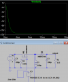
hey , this is my circuit i want to get a range of voutput voltage from -12V to -9V , the load is potentiometer of 100ohm , i pur in serios a resistor of 25ohm
because i dont want to get infinite current , so in my simulation i cant get this range in the two cases(Rmin/Rmax) i get almost the same voltage -9V
 

Attachments

DickCappels

Joined Aug 21, 2008
10,169
That appears to be an inverting boost converter assuming low resistance in the circuit. No buck.

Running at a constant duty cycle that is what you should see. If you make the on time a higher percentage of the switching cycle you can get higher voltage on the output. Normally converters like this have feedback through an error correction amplifier (with a reference) which adjusts the duty cycle to maintain the desired voltage.

Is three volts sufficient to drive the gate of M1?

Another question out of curiosity: Since you have V2 across the gate and source of M1, what role does R2 play?
 

Thread Starter

salha

Joined Jul 16, 2020
16
That appears to be an inverting boost converter assuming low resistance in the circuit. No buck.

Running at a constant duty cycle that is what you should see. If you make the on time a higher percentage of the switching cycle you can get higher voltage on the output. Normally converters like this have feedback through an error correction amplifier (with a reference) which adjusts the duty cycle to maintain the desired voltage.

Is three volts sufficient to drive the gate of M1?

Another question out of curiosity: Since you have V2 across the gate and source of M1, what role does R2 play?
I drive the gate from the PWM of raspberry pi I cant anderstarnd your first question, and i put the R2 to limit the current and to avoid damege for the raspberry pi ,i want shouldn't get -12V to -9V if i change the load from 25 to 125 ohm ?
I did that for BOOST converter and this worked at the same duty cycle .
I want this results because i am building a project to get at the output a bipolar voltage
 

DickCappels

Joined Aug 21, 2008
10,169
Constant duty cycle means constant output voltage if there are low losses particularly in the inductor.

I could not completely work out the part number of the MOSFET and consequently could not locate a datasheet. Do you know where I can find one?

Those inductors in Spice are perfect and they give pretty good voltage stability vs change in load. If you want to vary the voltage you will need to change the duty cycle, or if you want to vary the voltage as a function of the load, try adding some resistance to the inductor. You can do that by either adding a resistor in series with the inductor or by opening the inductor's dialog box and typing the resistance in. As I recall the default inductance in LTspice is zero ohms.
 

Thread Starter

salha

Joined Jul 16, 2020
16
Constant duty cycle means constant output voltage if there are low losses particularly in the inductor.

I could not completely work out the part number of the MOSFET and consequently could not locate a datasheet. Do you know where I can find one?

Those inductors in Spice are perfect and they give pretty good voltage stability vs change in load. If you want to vary the voltage you will need to change the duty cycle, or if you want to vary the voltage as a function of the load, try adding some resistance to the inductor. You can do that by either adding a resistor in series with the inductor or by opening the inductor's dialog box and typing the resistance in. As I recall the default inductance in LTspice is zero ohms.
in the real circuit i put this MOSFET FQP30N06L because of his low threshould voltage , and i add in the simulation in series a 0.4 ohm resistor and that works , so in the real circuit i add this resistor??
 

DickCappels

Joined Aug 21, 2008
10,169
in the real circuit i put this MOSFET FQP30N06L because of his low threshould voltage , and i add in the simulation in series a 0.4 ohm resistor and that works , so in the real circuit i add this resistor??
That depends on how you want it to work. You've seen the effects of a resistor in series with the inductor. If that it how you want your circuit to behave then add some resistance in series with the inductor if needed. Note: All inductors have some resistance, some more than others with the same inductance.

What you are doing is unconventional. If you are doing this for the experience then that is great, but if you are going to put it to use be aware that as the load changes so will the voltage and that could be a problem.

1594996424508.png
Pretend for a moment that the Arduino in the image above is a Raspbery Pi. If yours can generate pulse width modulation and has an analog-to-digital converter or a comparator you can take the voltage across the load and compare it with the desired voltage and gradually increase of decrease the pulse width. You would probably learn a lot in the process.

Incidentally, if your load is going to be under 1 amp then 3.3V will be plenty of gate drive.
 

Thread Starter

salha

Joined Jul 16, 2020
16
That depends on how you want it to work. You've seen the effects of a resistor in series with the inductor. If that it how you want your circuit to behave then add some resistance in series with the inductor if needed. Note: All inductors have some resistance, some more than others with the same inductance.

What you are doing is unconventional. If you are doing this for the experience then that is great, but if you are going to put it to use be aware that as the load changes so will the voltage and that could be a problem.

View attachment 212358
Pretend for a moment that the Arduino in the image above is a Raspbery Pi. If yours can generate pulse width modulation and has an analog-to-digital converter or a comparator you can take the voltage across the load and compare it with the desired voltage and gradually increase of decrease the pulse width. You would probably learn a lot in the process.

Incidentally, if your load is going to be under 1 amp then 3.3V will be plenty of gate drive.
you said my if my load going to be under 1 amp then 3.3V will be plenty of gate drive , you can explane that to me? the Ioutmax is 0.5A (this is my final project in college ).
 

Thread Starter

salha

Joined Jul 16, 2020
16
you said my if my load going to be under 1 amp then 3.3V will be plenty of gate drive , you can explane that to me? the Ioutmax is 0.5A (this is my final project in college ).
Sure I will add feedback and A/D at the output of the circuit like I did in BOOST, but it's important for me now to get the range of -9V to -12V when I change load, and then I will add feedback, because in my project I need to tap on a desired voltage in keyboard whose range is between 9 to 12 then get this voltage in both converters (BOOST & BUCK BOOST) should get bipolar voltage (+- the voltage)
 

DickCappels

Joined Aug 21, 2008
10,169
From the datasheet:
1595072500605.png
The threshold voltage is 2.5 volts max and the typical gain is about 24 amps drain current per volt of gate voltage. That is very encouraging.
1595072248454.png
The typical performance curves also show that we can expect to see an amp with 3 volts on the gate (Figure 2) and 3 volts on the drain (Figure 1).

I have the uneasy feeling that you are not going to get what you need from this circuit. To put my mind at rest: Why do you want the voltage to change depending upon the load?
 

Thread Starter

salha

Joined Jul 16, 2020
16
From the datasheet:
View attachment 212409
The threshold voltage is 2.5 volts max and the typical gain is about 24 amps drain current per volt of gate voltage. That is very encouraging.
View attachment 212408
The typical performance curves also show that we can expect to see an amp with 3 volts on the gate (Figure 2) and 3 volts on the drain (Figure 1).

I have the uneasy feeling that you are not going to get what you need from this circuit. To put my mind at rest: Why do you want the voltage to change depending upon the load?
The purpose of my load is to change the current, and I am asked in the project to show when I change the load the voltage at the output will not change by the control system of the RASPBERRYPI, I must first of all in the initial stage get the voltage range 9 to 12 when I change the load, to make sure Later in the project when I press the keyboard 9V/10V/11V/12V I will get these voltages.
 

Thread Starter

salha

Joined Jul 16, 2020
16
From the datasheet:
View attachment 212409
The threshold voltage is 2.5 volts max and the typical gain is about 24 amps drain current per volt of gate voltage. That is very encouraging.
View attachment 212408
The typical performance curves also show that we can expect to see an amp with 3 volts on the gate (Figure 2) and 3 volts on the drain (Figure 1).

I have the uneasy feeling that you are not going to get what you need from this circuit. To put my mind at rest: Why do you want the voltage to change depending upon the load?
i add like you said a resistor in series to the inductor in the simulation i get the desired voltages , tomorrow i will get the o.3ohm resistor from the
warehouse of the college and add it to my real circuit
 

Attachments

DickCappels

Joined Aug 21, 2008
10,169
It is like a specific output resistance, or basically, a resistor in series with a power supply.

I'll stay tuned in case you have any difficulties or questions.
 

Thread Starter

salha

Joined Jul 16, 2020
16
It is like a specific output resistance, or basically, a resistor in series with a power supply.

I'll stay tuned in case you have any difficulties or questions.
good morning , i am in the college and i add 0.3 ohm in series to the inductor but i get the range : -4 to -8 , that is because of my MOSFET? what i should change in my circuit?
 

Thread Starter

salha

Joined Jul 16, 2020
16
good morning , i am in the college and i add 0.3 ohm in series to the inductor but i get the range : -4 to -8 , that is because of my MOSFET? what i should change in my circuit?
I think that the problem is with the MOSFET i dont know , i order the SUP40012EL MOSFET i dont know if this gonna change any thing
 

Attachments

DickCappels

Joined Aug 21, 2008
10,169
Why do you think the MOSFET is the problem? I checked the datasheet you just posted and this MOSFET looks good,

What kind of inductor are you using?

If you have access to an oscilloscope you can check the drain of the MOSFET and if it is not going into saturation I will be surprised and you will have to find a different MOSFET and/or increase the drive voltage. If the drain voltage is a fraction of a volt, the MOSFET and its drive are not the problem. Did you already make that check this already?

I wrote most of the writing below before you sent you more recent post.

I take it your experimentation was done with Spice. The MOSFET might be part of the problem but the problem is probably the resistance of the inductor, which can be modeled as a resistor in series with the inductor.

You can probably compensate by measuring the resistance of the physical inductor and subtract that from your 0.3 ohm resistor. If it is over 0.3 ohms you know you need to get lower resistance inductor. Stay away from those small signal inductors and get something clearly designed to be used in a power supply and if you can, measure the peak current in your Spice model and get an inductor rated higher than that 1.3x the highest peak current to be safe .

Can you post you .asc model?
 

Thread Starter

salha

Joined Jul 16, 2020
16
Why do you think the MOSFET is the problem? I checked the datasheet you just posted and this MOSFET looks good,

What kind of inductor are you using?

If you have access to an oscilloscope you can check the drain of the MOSFET and if it is not going into saturation I will be surprised and you will have to find a different MOSFET and/or increase the drive voltage. If the drain voltage is a fraction of a volt, the MOSFET and its drive are not the problem. Did you already make that check this already?

I wrote most of the writing below before you sent you more recent post.

I take it your experimentation was done with Spice. The MOSFET might be part of the problem but the problem is probably the resistance of the inductor, which can be modeled as a resistor in series with the inductor.

You can probably compensate by measuring the resistance of the physical inductor and subtract that from your 0.3 ohm resistor. If it is over 0.3 ohms you know you need to get lower resistance inductor. Stay away from those small signal inductors and get something clearly designed to be used in a power supply and if you can, measure the peak current in your Spice model and get an inductor rated higher than that 1.3x the highest peak current to be safe .

Can you post you .asc model?
i will check that in the oscilliscope , i didnt check yet, and im using a 100uF of inductor (ferrit) and the resistance of the inductor is 0.1 ohm .
 

Attachments

DickCappels

Joined Aug 21, 2008
10,169
I asked about the waveform on the drain. I just realized should have said to check the source. Should be very close to the power supply voltage.
 
Top