controll for motorized ball valve with relays?

Thread Starter

salty joe

Joined Dec 14, 2010
43
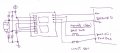
I need to open and close a 12V DC motorized ball valve. It has two wires and the polarity needs to be reversed to make the valve open and close. I think the drawing in the attachment should work, but is there a better/simpler way to control this valve?
 

Attachments

crutschow

Joined Mar 14, 2008
38,578
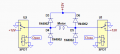
You can use two SPDT relays connected as an H-bridge, shown below:
The diodes are to prevent pitting/welding of the relay contacts from the motor inductive spikes.
If the motor requires more than a few amps, you may need to use higher current diodes (the 1N400x diodes are rated for 1A continuous, but will take much higher transient currents.)
upload_2019-9-30_18-20-11.png
_______________________________________________________________
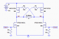
If you want to go solid-state, you could use a 2 N-MOSFET, 2 P-MOSFET H-bridge (below).
It doesn't require external transient-suppression, since the MOSFETs have built-in substrate diodes.
upload_2019-9-30_18-31-5.png
 
Last edited:

Thread Starter

salty joe

Joined Dec 14, 2010
43
Thank you very much crutschow!
Am I correct that I'd need only two pins from Arduino for either of your schematics to open and close the valve?
BTW, the motor is rated at only 80 mA.
 

dendad

Joined Feb 20, 2016
4,641
Yes, you will only need 2 pins.
I think the FET one does not have anything to prevent you turning both on together and shorting the battery.
It is a good idea to include limit switches, and nor just rely on motor stalling.
Add limit switches each end with diodes across them to allow drive in the other direction.
 

atferrari

Joined Jan 6, 2004
5,017
Yes, you will only need 2 pins.
I think the FET one does not have anything to prevent you turning both on together and shorting the battery.
It is a good idea to include limit switches, and nor just rely on motor stalling.
Add limit switches each end with diodes across them to allow drive in the other direction.
Sorry @dendad, could you show them in the schematic? Cannot visualize what you are suggesting.
 

crutschow

Joined Mar 14, 2008
38,578
Am I correct that I'd need only two pins from Arduino for either of your schematics to open and close the valve?
Yes.
If you use the MOSFET bridge, just make sure that both output aren't ever on at the same time, such as during power up or down.
If needed, you could add an interlock XOR gate to make sure that doesn't happen.
 

Thread Starter

salty joe

Joined Dec 14, 2010
43
I was going to go with the two SPDT relay version but I can't find SPDT relays set up for Arduino. The solid state version looks great but I don't know what type of limit switch to use or where to connect the 5V Arduino pin. Although I could solder it together, I'd need a lot of help on the solid state version and it seems like an awful lot to ask for.

Which brings me back to my primitive four SPST relay version. I have the spare Arduino pins on this sketch. I'm not much of a programmer but after a bit of goofing around, I can make things turn on and off at certain times. Other than using two more Arduino pins, are there major drawbacks to using four SPST relays?
 

Thread Starter

salty joe

Joined Dec 14, 2010
43
IDK why but I thought all those relays were SPST, oops and now I know the difference between SPST and SPDT.

Thanks a ton you guys, I really appreciate your generosity. Great schematics-so helpful.

Before I order parts, could I get a recommendation for a limit switch?
 

Thread Starter

salty joe

Joined Dec 14, 2010
43
I got the relay and limit switches and made myself somewhat familiar with limit switches.
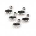
I don't think I can use limit switches because all the moving parts of the valve are enclosed. Unless I'm missing something, I have nothing to actuate the limit switch. I think the valve must have built in limit switches because if 12V is applied, the motor opens the valve and stops-no motor hum or anything.
 

MaxHeadRoom

Joined Jul 18, 2013
30,716
If this were a motorized valve, I am sure there would be some kind of open/closed sense of some kind, otherwise a motor could burn out.
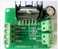
If on the extreme chance that the open closed had to be sensed then a H bridge with current sense output could be used, such as the LMD18200 avail for a couple of $$$ on ebay.
Max.
 

Attachments

With the two SPDT relay version, both relays on or both relays off is a permissible state and resuts in no movement. You also get dynamic braking in this configuration.

"chicken coop door" and "greenhouse window" searches should bring up oodles of these threads.

If you want to use a single bit to control, you can add another relay to get a simple open/close control or you can use a single DPDT relay that will do the reversing. Picture a DPDT toggle switch and cross the end terminals with 2 jumpers. Put power to the middle two and the valve to the center two. The DPDT relay will reverse the polarity and only one relay is needed.

If you do need limit switches, they can be placed in series with the OPEN/CLOSE coils. You get the added benefits of dynamic braking AND no power is consumed by activated coils unless the motor is moving.

12 V automotive relays are popular and cheap and have 30-40 Amp contact ratings. They have sockets to pigtails and have a dual socket version for use with power door locks which this essentially is.

The automotive relay coils do consume a fair amount of current and the limit switches have to be rated for this.

You may be able to go this L298 dual H-bridge driver chip https://www.amazon.com/Qunqi-Controller-Module-Stepper-Arduino/dp/B014KMHSW6 route.
 

MaxHeadRoom

Joined Jul 18, 2013
30,716
If you do need limit switches, they can be placed in series with the OPEN/CLOSE coils. You get the added benefits of dynamic braking AND no power is consumed by activated coils unless the motor is moving.

You may be able to go this L298 dual H-bridge driver chip https://www.amazon.com/Qunqi-Controller-Module-Stepper-Arduino/dp/B014KMHSW6 route.
The LMD18200 does not require LS. if current limit used.
If using L.S. with two wire to motor the L.S's will need a 'steering' diode across each
Max.
 
Top