Constant current at several hundred volts DC from batteries

MisterBill2

Joined Jan 23, 2018
27,741
A god
I would suggest using a square wave at a non-line frequency (or its harmonics). That would allow a correlation function between the detected current and the squarewave which would eliminate much of the noise.
A very good place for a square wave inverter!! That would also be cheaper and simpler to regulate. Probably much lighter than all of those batteries.
 

Thread Starter

sirch2

Joined Jan 21, 2013
1,071
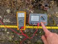
Just thought I'd feed back on this since there is some interest. I did some tests earlier in my soggy lawn with an insulation tester providing the current source (1.37mA at 250V) and took some potential readings using a Wenner array set up.

With a 1m probe spacing and no current injection I was getting a potential of -31.7mV (I assume this is galvanic?), with the Insulation tester injecting current I got 15.3mV so a change of 47mV. A 2m probe spacing gave a difference of around 30mV. So it looks like t is possible to get results with much lower current, at least in very wet ground. However doing the calcs; the 1m spacing gives 168 Ω/m and 2m gives 273Ω/m so quite a difference. Looks like I need to do more tests.

Here's some photos

PXL_20251205_114033554.jpgPXL_20251205_114033554.jpg

PXL_20251205_114138010.jpg
 

MrChips

Joined Oct 2, 2009
34,953
Be careful with your units.

Resistivity ρ = resistance R x area A / length L

Hence the unit of resistivity is Ωm, not Ω/m.
 

timm27

Joined Dec 11, 2020
27
Remember the adage: Volts jolts but mills kills. A current of less than 10mA across the body can put your heart into VF (ventricular fibrillation) and higher current can cause cardiac arrest. In either case without immediate medical intervention death is almost inevitable.

With an AC supply of maybe 10 - 20 volts and a correlation current measurement you should be able to get good measurements with microamp resolution. It would be interesting to measure both in-phase and quadrature currents and look into the effect of inductive/capacitive components of soil impedance.
 

MisterBill2

Joined Jan 23, 2018
27,741
Now I am interested in this. I have a well grounded radio tower , a neutral ground on my mains entrance, and a galvanized steel fence with grounded galvanized steel posts (not cemented, directly in the hard ground.) I may investigate if the weather is decent.
 
I've a half baked idea to make my own geophysics resistivity system and am wondering about the feasibility of creating a constant current DC source at a few hundred volts from batteries. Commercial units are available but they cost in the £1000's so I'm wondering what components I'd need to make such a constant current supply. Obviously the voltage can be achieved as used on insulation testers but I'm guessing they don't have current regulation.

Any pointers, I'm happy to research but don't really know where to start or what would be a good approach.
You should use common emitter bjt configuration
 

MisterBill2

Joined Jan 23, 2018
27,741
One additional consideration, prompted by seeing the photos, is that if this is any sort of populated area with mins power provided to multiple buildings in the area, then the mains distribution system will add a considerable influence to whatever voltages are measured.
Consider that the actual "Ground" is a very large plane with a large number of unknown connections from mains related sources AND a variety of unknown DC connections from unknown sources.
So it is not likely that the measurements made near any civilized area will correctly allow accurate resistivity measurements.
What may be interesting indeed will be a measurement of voltage reading with no power application at all. The results will probably be quite educational.
But most likely the results may not be very useful, unless you spot some electrical power leak being present.
 

Ian0

Joined Aug 7, 2020
13,158
One additional consideration, prompted by seeing the photos, is that if this is any sort of populated area with mins power provided to multiple buildings in the area, then the mains distribution system will add a considerable influence to whatever voltages are measured.
Consider that the actual "Ground" is a very large plane with a large number of unknown connections from mains related sources AND a variety of unknown DC connections from unknown sources.
So it is not likely that the measurements made near any civilized area will correctly allow accurate resistivity measurements.
What may be interesting indeed will be a measurement of voltage reading with no power application at all. The results will probably be quite educational.
But most likely the results may not be very useful, unless you spot some electrical power leak being present.
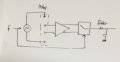
That’s why I would suggest using AC at a non-mains frequency, and synchronising the detector with the frequency of the injected current.
IMG_2084.jpeg
 

Thread Starter

sirch2

Joined Jan 21, 2013
1,071
One additional consideration, prompted by seeing the photos, is that if this is any sort of populated area with mins power provided to multiple buildings in the area, then the mains distribution system will add a considerable influence to whatever voltages are measured.
Consider that the actual "Ground" is a very large plane with a large number of unknown connections from mains related sources AND a variety of unknown DC connections from unknown sources.
So it is not likely that the measurements made near any civilized area will correctly allow accurate resistivity measurements.
What may be interesting indeed will be a measurement of voltage reading with no power application at all. The results will probably be quite educational.
But most likely the results may not be very useful, unless you spot some electrical power leak being present.
As I noted above I was getting -31.7 mv with no current injection so I guess that could be mains related. The actual application I intend for this is 1km or so from the nearest mains electricity
 

MisterBill2

Joined Jan 23, 2018
27,741
Even at 1Km distance I suggest checking for any voltage presence before making any resistance measurement. Easy to do, and also informative.
 
Top