connecting transistors

Audioguru

Joined Dec 20, 2007
11,248
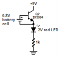
Please sketch how you connected an AA battery cell to the BE junction of the transistor without blowing up the base-emitter. The maximum allowed voltage to a base-emitter is only 0.9V for a little transistor. A new AA alkaline cell is 1.5V so maybe your battery was almost dead.

I do not see how biasing the BE from a 1.5V battery will make the transistor light an LED.
 

Thread Starter

gerases

Joined Oct 29, 2012
186
I connected the plus of the battery to the base and the minus to the emitter (the emitter being the arrowed line). The battery was almost dead.

I do not see how biasing the BE from a 1.5V battery will make the transistor light an LED.
It did for sure. Why wouldn't it?
 
Last edited:

Thread Starter

gerases

Joined Oct 29, 2012
186
Maybe the collector of the transistor was still connected to +9V but you didn't say that.
Sorry, that's what I meant by that VCC label on the collector. Yes, your drawing is correct. That's the setup. Is it wrong?
 

Audioguru

Joined Dec 20, 2007
11,248
Sorry, that's what I meant by that VCC label on the collector. Yes, your drawing is correct. That's the setup. Is it wrong?
Yes the circuit is WRONG.
Nothing limits the base-emitter current. If a new battery cell was used then the base-emitter would have blown up by the 1A or more of current.
You are lucky that the high internal resistance of the dead battery limited the current.
 

Thread Starter

gerases

Joined Oct 29, 2012
186
Yes the circuit is WRONG.
Nothing limits the base-emitter current. If a new battery cell was used then the base-emitter would have blown up by the 1A or more of current.
You are lucky that the high internal resistance of the dead battery limited the current.
Point taken. Do you see why the LED segment doesn't light up without the battery?

Could it be because the rest of the segments were lit up directly from the 4026 at that time?

Funny enough, my wife asked me to replace the batteries in the camera flash just before that -- and that's the battery I used.
 

Audioguru

Joined Dec 20, 2007
11,248
Could it be because the rest of the segments were lit up directly from the 4026 at that time?
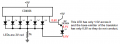
Because you used only one resistor from the common cathodes to ground instead of a resistor in series with each segment like you are supposed to do.
The base-emitter of the emitter-follower reduced the voltage to your LED so the LED did not have enough voltage to draw current and light.
 

Attachments

Thread Starter

gerases

Joined Oct 29, 2012
186
Because you used only one resistor from the common cathodes to ground instead of a resistor in series with each segment like you are supposed to do.
Well see, now I see why I shouldn't have! I think it's great!

The base-emitter of the emitter-follower reduced the voltage to your LED so the LED did not have enough voltage to draw current and light.
Thanks for the sketch. Very helpful. I think I understand, but correct me if I'm wrong:

In the emitter-follower configuration we calculate the voltage drops starting from the load and going up to the +? So, I gather, the 1K resistor took too much voltage, leaving too little to the LED and the BE junction? Only this way of calculating voltage drops could explain why the BE junction didn't get 0.6.
 

KrisBlueNZ

Joined Oct 17, 2012
111
But wouldn't connecting the LED with its positive end to the positive rail and the negative end to the output pin constitute putting voltage into an output pin?
Yes, pretty much.
The distinction between "putting voltage into" and "putting current into" a pin (or anything) is that when you "put voltage into" a pin, you are not expecting the pin to sink or source any (significant) current, and you don't deliberately limit the current flow (although the driving circuit often will limit the current as a by-product of how it is designed). You expect that the pin will not affect the voltage you apply (much), and you don't expect significant current to flow into it. This is true of INPUTS in general, except low-impedance inputs which are used for RF and high-speed data and are a special case.

When you're working with an output pin, you expect it to source and/or sink a certain amount of current. If you're driving a component such as an LED, you normally limit the current, to prevent damage to both the output and the LED.

It's not blown out because if I connect the output of 4026 directly to the segment, it lights up. Same if I bias the BE junction with a battery. A quick and dirty drawing attached. The GND from pin 2 of the LED array is the common cathode. Pin 3 is the segment pin. Pin 3 on 4026 is the output of the counter.
In those cases, the internal resistance of the voltage source is limiting the current that the LED receives. This may or may not be a safe thing to do. In the case of 4000-series CMOS outputs, the characteristics of the MOSFETs in the device mean that it just CAN'T source or sink much current - even if you short the output to VDD or VSS, the current is only around 10 mA or somewhat more. But this forces the MOSFET in the output stage to dissipate power, and that may be significant.

For example, take a 4026 running at 12V with its output connected to a LED to ground with no limiting resistor. Let's say the output current is 30 mA (it's higher at higher supply voltages) and the LED drops 2V. The MOSFET in the output stage therefore is forced to have 10V across it (12V - 2V) and 30 mA flowing through it; from P = V I this means it is forced to dissipate 300 mW, which will make the 4026 get hot. This is obviously not good practice!

When you connect a battery to an LED, the current is limited by the internal resistance of the battery. For a 9V PP3-type battery (the small ones with the snap-on connector at the top), internal resistance is significant, and increases greatly as the battery goes flat. This will limit the current, but you could still damage the LED if you use a new battery.

In the general case, forcing an output to a certain voltage by connecting it to VDD, VSS, VCC or GND, either directly or through a semiconductor junction such as an LED, is not done.

Is the high resistance because of the internals of the chip or the load?
The chip. If you connect an LED to a voltage source that's significantl higher than the LED's forward voltage (~2V for a red LED) without a current limiting resistor, the current that flows is limited only the internal resistance of the voltage source.

Back to my original question of connecting the transistor to the 7-segment LED. Last night I tinkered with it and got unexpected results. I connected everything the way you suggested: using the emitter-follower arrangement. The output pin of the 4026 goes to the base, the collector to the positive rail, and the emitter to the the positive of the segment LED. I left a 1K resistor on the common cathode, so the emitter was connected directly to the segment pin. The voltage on the output pin of the 4026 was 8.6V (the power supply is 9V). My transistor has an hfe of at least a 100. So my thinking was, I need 16mA for the LED. If I get 16mA/100 on the base, I'll be good. So, the resistor value on the base is:
(8.6 - 0.6) / 0.00016 = 50K. Sounds a lot but what the heck, I'll try it.
You don't need a series resistor on the base for the emitter follower. The base will not draw significant current. The base will only draw as much current as the transistor needs in order to pass the collector-emitter current that you're drawing out of it.

Here are the calculations for your circuit.

The 4026 output, and the base (because you don't need a series resistor there) are 8.6V. The emitter will be about 0.7V below that, i.e. 7.9V. The segment will drop, say, 2V. Therefore the voltage remaining across the current limiting resistor (between the emitter and the segment) will be about 5.9V.

If you're using 1K as the segment current limiting resistor, you'll get about 5.9 mA, which is probably on the low side. With an HFE of at least 100, the base current will be 59 uA (microamps) or less. That is not a significant load on the 4026's output pin. Everything will be OK.

When I connected everything together, the segment didn't light up. I measured the BE voltage and it was 0.5V. So, the CE path of the transistor is probably closed (i.e., the CE switch is open).
I would have said "the transistor is not conducting" or "the transistor doesn't have enough base bias to turn ON".
At this point, I'm not really sure what to do. I go for a 33K resistor, then lower, all the way to 1K -- same thing and same voltage drop of 0.5V.
I think you must have made a mistake. Even with a 50k resistor between the 4026 output and the base, the segment should have lit up, because the base current is so low that it will cause only a small voltage drop across the base resistor. But you don't need that resistor. That is a significant advantage of the emitter follower in this situation, compared to a common emitter configuration.

I took an AA batery and biased the BE junction from it. The segment lit up quite brightly.
Well you must have something right. But don't do that; an AA battery can supply quite a lot of current, and connecting a voltage source across a semiconductor junction in the forward direction will cause significant current to flow (as I explained earlier), and can easily damage the transistor.

Perhaps your transistor has been damaged by excess base-emitter current. That would explain why the 4026 circuit doesn't work. Think of the damaged transistor as having a very low HFE, so it needs a LOT of base current to make it conduct.

One last thing I tried was: leaving the output of the 4026 on the base with a 33K resistor, I connected a stand-alone LED using the same arrangement (emitter-follower) and the LED lit up as well.
So an LED in place of the segment DOES light up? In that case, if you haven't made a wiring error, you've probably damaged the seven segment display.

As a general guide, you should use a current limiting resistor in series with any semiconductor junction (base-emitter of a transistor, or an LED or a segment) when you're driving it from an output or a voltage source.

So, why doesn't the segment light up? I'm thinking that the LED array takes too much voltage somehow and the transistor can't get biased enough. It occurred to me on the way to work that I should have tried upping the supply voltage to 12V.
That's possible too. Perhaps the segment in the display consists of several LED elements in series; in that case, each LED needs 2V (or whatever, according to colour) across it, and those voltages add together. So yes, it may need more voltage than a single LED.

Of course if you posted the part number of the display here, we could tell you.

Edit: FWIW my opinion on "break things and learn" vs. "never do it wrong" is that when you're learning, breaking things is nearly unavoidable and a useful part of the learning process. As wayneh said, you will remember the lesson well. It's part of the normal process of finding the boundaries of what's safe by sometimes crossing them! Of course it's not good if you do a lot of damage, or break something expensive, or hurt yourself (which is why the rules are different when you're working with high voltages); also, it causes confusion if you don't realise that you've damaged a component, then can't figure out why your circuit isn't working as it should. That's another lesson you're learning. So don't feel bad about it. You're not working in a professional environment yet!

Edit 2: Regarding placement of the segment current limiting resistor, if you use a single resistor between the common cathode and 0V the circuit will work, but (a) component variations CAN cause different segments to light at different brightnesses, and (b) the more segments that are lit, the dimmer each segment will be. Neither of these things are acceptable in a "proper" design; you need a separate resistor for each segment.
 
Last edited:

Thread Starter

gerases

Joined Oct 29, 2012
186
Of course if you posted the part number of the display here, we could tell you.
I'll be back later but here's the part number:
Kingsbright BC56-11EWA

Have to re-read your response carefully :)
 

KrisBlueNZ

Joined Oct 17, 2012
111
I'll be back later but here's the part number:
Kingsbright BC56-11EWA
That seems to have only one LED per segment, so you should be fine with it.

Re-reading your fault description, and assuming you didn't make any wiring errors, I think either your display, or your transistor, or both, may have been damaged by overcurrent. I would get a new display and some new transistors, and rewire your breadboard starting from scratch. If it doesn't work, post a close-up photo of the breadboard. If it does, try swapping in the old components one at a time, and throw out the ones that don't work.
 

Thread Starter

gerases

Joined Oct 29, 2012
186
Well, I disconnected everything from all counters and the LED array except one connection from 1 counter for 1 segment. I removed the common cathode resistor and moved it to the emitter -- voila, it worked. Not sure what was the reason precisely, but I'm OK with this result.

Interestingly enough, the segment lit up even without the collector connected to the positive rail. I.e., the base-emitter current was enough to light up the LED segment! The current was 4mA. When I connected the collector, the current became 6mA and it was noticeably brighter.

In the general case, forcing an output to a certain voltage by connecting it to VDD, VSS, VCC or GND, either directly or through a semiconductor junction such as an LED, is not done.
What is VDD and VSS?

Alright, another question. In the emitter follower configuration with an NPN transistor, is it true that we calculate voltage drops starting from the ground, (i.e. the emitter load) and including the base-emitter junction while in the common emitter configuration the voltage drops are calculated from the plus (i.e. the collector load) excluding the BE junction?

I noticed that when I went higher on the LED resistor, eventually neither the transistor could get enough bias nor the LED -- and so nothing lit up. It happened with a 100K for example. What would be the math behind calculating voltage drops in this configuration?
 

Audioguru

Joined Dec 20, 2007
11,248
Interestingly enough, the segment lit up even without the collector connected to the positive rail. I.e., the base-emitter current was enough to light up the LED segment! The current was 4mA. When I connected the collector, the current became 6mA and it was noticeably brighter.
Guess what? The base-emitter is a diode. When the collector is not connected then the current from the output of the CD4026 goes through the "diode" and into the LED.

What is VDD and VSS?
The CD4026 IC is Cmos and is made with Mosfets.
The positive terminal on an N-channel Mosfet is its Drain so the voltage is called VDD.
The negative terminal on an N-channel Mosfet is its Source so the voltage is called VSS. The Cmos ICs also have their positive power supply pin called VDD and the negative pin is called VSS.

In the emitter follower configuration with an NPN transistor, is it true that we calculate voltage drops starting from the ground, (i.e. the emitter load) and including the base-emitter junction while in the common emitter configuration the voltage drops are calculated from the plus (i.e. the collector load) excluding the BE junction?
No, because frequently a common-emitter transistor also has an emitter resistor.

I noticed that when I went higher on the LED resistor, eventually neither the transistor could get enough bias nor the LED -- and so nothing lit up. It happened with a 100K for example. What would be the math behind calculating voltage drops in this configuration?
Ohm's law says that a high resistor value passes less current.
Common sense says that low current in an LED reduces its brightness.

But our hearing's and vision's response to loudness and brightness are not linear, it is logarithmic so they have a very wide range: a distant whisper and a nearby jet airplane; moonlight and sunlight.

With the 100k resistor in series with the LED then it lighted but it was very very dim.
 

Thread Starter

gerases

Joined Oct 29, 2012
186
With the 100k resistor in series with the LED then it lighted but it was very very dim.
Thank you for the response. More later, but I was wondering, with a 100K resistor and a 9V supply what are the voltage drops across:

the resistor,
the led,
the BE junction

How big should the resistor be for the BE junction to stop being biased enough?
 

wayneh

Joined Sep 9, 2010
18,183
The drop across the diodes is more-or-less fixed by the properties of the diode. (It does vary with current and temperature, but not a lot.)

So the transistor B-E drop is about 0.65 while the LED drops 3.3V or so, depending on color.

The drop across the resistor is what's left, and current is then calculated by the remaining voltage divided by the resistance.
 

Thread Starter

gerases

Joined Oct 29, 2012
186
So the transistor B-E drop is about 0.65 while the LED drops 3.3V or so, depending on color.
Well, the B-E and the LED dropped less and less the higher the resistor was. That's why I'm asking.
 

wayneh

Joined Sep 9, 2010
18,183
If you study the diode equation and how the Vf of an LED varies with current, you'll see there is an effect of current on both. At the very low current you're talking about, perhaps these effects are steeper than in normal operating range.

Still, I'm surprised you saw much variation. How much are you talking about?

And don't forget, as the current gets very small, it becomes harder to get accurate readings since the meter alters the circuit.
 

Thread Starter

gerases

Joined Oct 29, 2012
186
Well, at 100K the BE junction became something like 0.5 and the LED was around 1.5 or so, but I can't trust my memory on the LED -- it was low for sure.
 

Audioguru

Joined Dec 20, 2007
11,248
...with a 100K resistor and a 9V supply what are the voltage drops across:

the resistor,
the led,
the BE junction
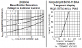
The datasheets show graphs of the "typical" voltages at different currents but yours might be a little lower or higher than the "typical".

Your transistor is used as a saturated switch, not as a linear amplifier so its base current should be 1/10th the collector current.
With a collector current of 100mA and a base current of 10mA the typical VBE is almost 0.9V.
With a base current of 0.1mA then it is a little more than 0.6V.
The graph shows how much the voltage drop changes when the temperature changes.

At a very low current, your LED is probably 1.5V and the transistor voltage drop is almost zero so the 100k resistor in series between them had 7.5V which produced a current of 7.5/100k= 75uA which is very small for an LED.

How big should the resistor be for the BE junction to stop being biased enough?
Most transistors turn on well when the base current is 1/10th the collector current.
 

Attachments

Top