INA219 Not Connecting: I2C Scan Returns All Addresses (0x08 - 0x77) on Pi Pico

Thread Starter

enginmit8390

Joined Jul 2, 2026
3
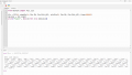
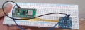
I'm trying to connect an INA219 current sensor to a Raspberry Pi Pico using MicroPython in Thonny, but I'm running into an issue where the I2C bus scan floods and returns every single possible address from 0x08 to 0x77 instead of just finding 0x40.

My Setup:

  • Microcontroller: Raspberry Pi Pico
  • Sensor: INA219 breakout board


What I've tried so far:

  1. Running the scan script with the INA219 completely disconnected returns an empty list []. The flood only happens when the board is plugged in.
  2. It randomly detected properly as 0x40 once during an early run, but now it only returns the full list of addresses.
  3. Verified the header pins are soldered.
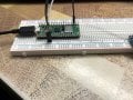
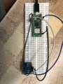
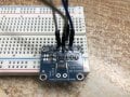
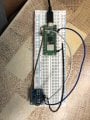
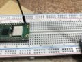
I have attached my code output and pictures of my wiring/soldering setup below. Any ideas on what might be causing the lines to pull down or float like this?

Thank you!code_thonny.pngIMG_2301.jpegIMG_2299.jpegIMG_2303.jpegIMG_2300.jpegIMG_2302.jpeg
 

panic mode

Joined Oct 10, 2011
5,426
you did not wire it correctly. you have to add pair of pull-up resistors on both I2C lines. 4k7-5k6 is fine (up to 10k). depending on module variant, there may be on-board 10k pull-ups. if they are present but lines are floating / sinking, they are not doing the job. i have board with 5 of those ICs and pair of 5K1, no problem.

btw, while breadboards are handy, they are notorious for poor connections, specially if some larger wire was inserted in specific opening. try relocating your modules and wires to slightly different place on same breadboard.
 
Last edited:

panic mode

Joined Oct 10, 2011
5,426
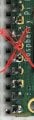
upon closer inspection, SDA and SCL seem to be swapped around. also the soldering job on those headers is really dodgy.

This is typical connection:
  • INA219 VCC → Pico 3.3V (Pin 36) BLUE WIRE
  • INA219 GND → Pico GND (e.g., Pin 38). BLACK WIRE... if my interpretation is correct, you used GND on pin 23. that should be fine.
  • INA219 SCL → Pico I2C0 SCL / GP4 (Pin 6) BROWN WIRE. this should go to pin 6, but photo shows it goes to 7 of RPI.
  • INA219 SDA → Pico I2C0 SDA / GP5 (Pin 7) WHITE WIRE. this should go to pin 7, but photo shows it goes to 6 of RPI.
  • INA219 VIN+ → Power supply or battery positive
  • INA219 VIN- → Load / device positive (completing the circuit)
 

izumi0707

Joined Jul 4, 2026
1
Please share:

The exact MicroPython code you're using for the I2C initialization and scan.
A clear photo of your wiring (showing the Pico and INA219 connections).
The specific INA219 breakout board model or a link to where you bought it.

The output of: print(i2c.scan())
(or confirm it literally returns every address from 0x08 to 0x77).

With those details, it's usually possible to narrow the cause down quite quickly.
 

Thread Starter

enginmit8390

Joined Jul 2, 2026
3
I'm trying to connect an INA219 current sensor to a Raspberry Pi Pico using MicroPython in Thonny, but I'm running into an issue where the I2C bus scan floods and returns every single possible address from 0x08 to 0x77 instead of just finding 0x40.

My Setup:

  • Microcontroller: Raspberry Pi Pico
  • Sensor: INA219 breakout board


What I've tried so far:

  1. Running the scan script with the INA219 completely disconnected returns an empty list []. The flood only happens when the board is plugged in.
  2. It randomly detected properly as 0x40 once during an early run, but now it only returns the full list of addresses.
  3. Verified the header pins are soldered.
I have attached my code output and pictures of my wiring/soldering setup below. Any ideas on what might be causing the lines to pull down or float like this?

Thank you!View attachment 368980View attachment 368981View attachment 368982View attachment 368983View attachment 368984View attachment 368985
 

Attachments

Top