Connecting HC-SR505 (PIR) to relay module

Thread Starter

wodrith

Joined May 5, 2011
18
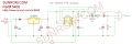
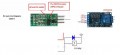
I am trying to connect the PIR with a S8050 transistor to the relay module board. The PIR documentation shows the bottom image with the output of the PIR connected to the 12V rail through a diode and also connected to the relay. I'm assuming one of the 12V connections to the relay is the input power and the other connection to the relay is


Untitled.png
 

Attachments

ericgibbs

Joined Jan 29, 2010
18,872
hi,
Please post a complete diagram showing how the modules and power are inter connected,

Clips from photo's are not helpful.

E
 

Thread Starter

wodrith

Joined May 5, 2011
18
I did, post 17

I’m trying to post the clips to understand what the documentation means. Post 17 is the exact connections. The diode I put in you asked why, there is a diode in the PIR documentation being used. I’m trying to understand how to connect the circuit according to that documentation. I made a note that in post 17, the PIR was the soldered on transistor, like mentioned in the PIR documentation option 2.

you asked me to show you the transistor circuit, I don’t know it. I followed the PIR documentation to solder it to the board.
 

eetech00

Joined Jun 8, 2013
3,961
If you modified the board correctly, the boards should be wired together like this.
1593289785156.png

You don't need the diode. When the relay is directly connected to the PIR or transistor, the diode suppresses back EMF coming from the relay coil so it doesn't damage the PIR or transistor.
However, you need to verify the PIR output level when motion is detected. DO THIS BEFORE WIRING THE BOARDS TOGETHER.
Measure the voltage at the PIR "OUT" pin when motion is detected and not detected.
Report back your findings.
 
Last edited:

Thread Starter

wodrith

Joined May 5, 2011
18
Thanks!

I have to wait until Monday to measure this, as I am away from my project.

I did measure it before hooking it up to the relay. When the PIR detects motion, it outputs ~3.3 for ~8 seconds. When not motion is in front of it for more then 8S, it outputs 0V. I'll post an update Monday evening.
 

eetech00

Joined Jun 8, 2013
3,961
Thanks!

I have to wait until Monday to measure this, as I am away from my project.

I did measure it before hooking it up to the relay. When the PIR detects motion, it outputs ~3.3 for ~8 seconds. When not motion is in front of it for more then 8S, it outputs 0V. I'll post an update Monday evening.
Were those measurements done after you modified the PIR module?
 

Thread Starter

wodrith

Joined May 5, 2011
18
They were not, I need to measure them with the modification (I made it, then didnt measure or hook the circuit up), as I assume I should be measuring 9V (Or whatever Vin is) when detecting motion, then 0V when not?
 

Thread Starter

wodrith

Joined May 5, 2011
18
@eetech00 I measured the voltage with the transistor added and the indicated resistor removed.

Voltage when not detecting motion
Between + and GND: 9V
Between OUT and GND : ~100mv
Between OUT and +: ~100mv

Voltage when not detecting motion
Between + and GND: 9V
Between OUT and GND : ~5mv
Between OUT and +: 9V

Multi-meter ground on OUT, and positive on +
 

eetech00

Joined Jun 8, 2013
3,961
@eetech00 I measured the voltage with the transistor added and the indicated resistor removed.

Voltage when not detecting motion
Between + and GND: 9V
Between OUT and GND : ~100mv
Between OUT and +: ~100mv

Voltage when not detecting motion
Between + and GND: 9V
Between OUT and GND : ~5mv
Between OUT and +: 9V

Multi-meter ground on OUT, and positive on +
which measurement is when motion is detected??
 

Thread Starter

wodrith

Joined May 5, 2011
18
Oops... I am a dummy

Voltage when not detecting motion
Between + and GND: 9V
Between OUT and GND : ~100mv
Between OUT and +: ~100mv

Voltage when detecting motion
Between + and GND: 9V
Between OUT and GND : ~5mv
Between OUT and +: 9V

Multi-meter ground on OUT, and positive on +
 

eetech00

Joined Jun 8, 2013
3,961
It looks like EricG was right. The new transistor inverted the output.
According to your measurements, the PIR "out" terminal switches from "open" to "ground" when motion is detected. Your relay module wants a high signal to trigger it "on". You'll either need to add an external transistor to invert the signal, or maybe you can change the trigger level in the relay module software.

But if you want, you could probably drive a relay directly from the PIR "OUT" terminal now.:D
 

Thread Starter

wodrith

Joined May 5, 2011
18
@dendad , that is what I just tried. Relay trigger and the 6v-30v input are tied together and attached to the 9V source. Trigger ground is connected to relay out.

PIR senses motion, 9v is measured across trigger and trigger ground, relay fires. After programmed delay, relay resets, and stays reset until PIR goes from not detecting motion, to detecting motion again.

I’m utilizing these two components to control some holiday animatronics. The sensors that come with them are garbage for triggering and usually light sensitive... terrible for flashing lights. The relay board gives me some options I like, ex. triggering for a set ON time, and allowing me to specify an off time where the board ignores triggers. That allows me to better control how often things trigger. I also have some modular cable harnesses so I can place the sensors more where I want activations.

I have one more issue I’m working through. The PIR sensor has a controller in it that specifies how long to hold the PIR output. For the SR505, that is 8s +- 30%. Since I am utilizing the relay module to be the smarts... having the PIR not have such a long output delay is more advantageous. The SR501 module I didn’t get has a potentiometer to adjust this. I went with the SR505 specifically for the form factor as it smaller and looks easier to waterproof.

I figure I can replace the correct capacitor or resistor with the right value to change the RC constant going to the PIR controller IC to reduce how long this delay lasts. Figuring out this resistor or cap is my next goal.
 

Thread Starter

wodrith

Joined May 5, 2011
18
So... I am trying to figure out how to adjust the turn on delay of this circuit. I'm looking at page 9 of the EG4001 documentation. Im including a snip for convenience.

eg4001_page8.png

And a snip of the SR505 schematic:
PIR.png

So, with Rt as 150K, and Ct .1uf I'd have

Output delay time = Wolfram Alpha Calculation Link which gives us 692 seconds. Must be the schematic is wrong? I'd expect the .1uF cap to be a 1nF cap. I can measure this when I get back around the circuit again to verify.

I'd imagine I'd want something like a 150pF cap if I wanted a 1s long trigger. maths
 

Attachments

Top