When I connect the white line with the coin acceptor switched to NO I get -.45V. When i switch the coin acceptor to NC i get +11.8 volts. When i put a coin in with the coin acceptor on NO, the meter goes from -.45 to 2.8ishV
What does the voltage measure when a coin is inserted and how are you reading this voltage?
This is on the output of the COIN pin correct?
What setting are you using for the pulse width?
What does the voltage measure when a coin is inserted and how are you reading this voltage?
This is on the output of the COIN pin correct?
What setting are you using for the pulse width?
Is this 3.4 volt reading when connected to the + trigger input?
Normally I would set the pulse duration at max, 100ms.
What happens if you connect the COIN output set on NC to the - trigger input?
Post a link to the relay module please.
Have you experimented to see what voltage is required to trigger that pulse-relay device? And to see what the pulse duration must be? It is entirely possible that the pulse is not adequate to trigger your relay.
Is this 3.4 volt reading when connected to the + trigger input?
Normally I would set the pulse duration at max, 100ms.
What happens if you connect the COIN output set on NC to the - trigger input?
Post a link to the relay module please.
Have you experimented to see what voltage is required to trigger that pulse-relay device? And to see what the pulse duration must be? It is entirely possible that the pulse is not adequate to trigger your relay.
Unfortunately there is probably no information at all about that "relay module" from the supplier. If it came from amazon you are out of luck for sure.
From the info I found the +trigger requires 12 volts on that unit. Appears the trigger input is loading down the output from the acceptor.
Might be able to add a transistor to amplify the coin output.
From the info I found the +trigger requires 12 volts on that unit. Appears the trigger input is loading down the output from the acceptor.
Might be able to add a transistor to amplify the coin output.
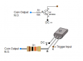
I'm thinking this scheme using a npn transistor like a 2N3904 and a 10K resistor.
Using the NO coin output to activate the transistor which inverts the signal to trigger the - input.
What components do you have on hand?
I'm thinking this scheme using a npn transistor like a 2N3904 and a 10K resistor.
Using the NO coin output to activate the transistor which inverts the signal to trigger the - input.
What components do you have on hand? View attachment 320986
I'm still thinking it might be possible to use the Counter output. Can you get a voltage reading when a coin is inserted in both NO and NC positions NOT connected to the relay module ?
I'm still thinking it might be possible to use the Counter output. Can you get a voltage reading when a coin is inserted in both NO and NC positions NOT connected to the relay module ?
I should have started off by saying this is what I want to create. Do you think there is a better way than using a relay to create something like this? Maybe not so much with the lights and all just the coin acceptor
Unfortunately I can't read that language but it seems if a motor and timing are required a relay would be appropriate.
With a little more data from coin acceptor I believe you can make it work.

 Facebook
 Google
 GitHub
 Linkedin