
 Facebook
 Google
 GitHub
 Linkedin
So I am trying to test a small pulsing board connected to a thermal actuator to see if the pulsing board actually reduces the overall current used. I think the current surge every time there is a pulse might outweigh the benefit of the off time. (BTW I don't have a great deal of electrical knowledge, i'm a learner)
The board is 24 VAC so I have a Voltage regulator supplying 24VAC from mains to the board. I input a small resistor after the thermal actuator to use as a shunt resistor and hopefully get my readings from (Not sure if this is the right thing to do).
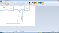
So the question is how to I connect up my oscilloscope to get a reading without blowing the fuse? Here is my diagram with the oscilloscope as I incorrectly wired it.
Can any one help? How do I connect it? Why is it shorting as it is? is there a better way of doing it?
Thanks in advance!!
The board is 24 VAC so I have a Voltage regulator supplying 24VAC from mains to the board. I input a small resistor after the thermal actuator to use as a shunt resistor and hopefully get my readings from (Not sure if this is the right thing to do).
So the question is how to I connect up my oscilloscope to get a reading without blowing the fuse? Here is my diagram with the oscilloscope as I incorrectly wired it.
Can any one help? How do I connect it? Why is it shorting as it is? is there a better way of doing it?
Thanks in advance!!


 I always thought there should be a return path or a GROUND..






