Facebook
 Google
 GitHub
 Linkedin
Hi. First of all; I'm new to this forum, but I'm very interested in learning electronic. I've done some simple Arduino projects earlier, and have basic eletronics knowledge.
I need some help to figure out which IC's and what other components to use.
The case:
I appreciate every help I can get.
Thank you.
I need some help to figure out which IC's and what other components to use.
The case:
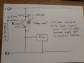
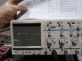
- I wan't to read PWM-pulses from a motor speed sensor (3-pin hall sensor). It's a 12V system, so it changes between 0-12V. (I need to reduce the voltage from 12V to 5V, so that an Arduino can read it) Typically, at 10 km/h, the frequency is about 160 Hz. See attached picture for readings from oscilloscope.
- Then I have to count the pulses, and then "scale the frequency" output with a numerical value in the software. Example: If I read 200 Hz into the Arduino, then I must multiply it with a contant so I get a 300 Hz output from the Arduino.
- The new, transformed PWM output from the Arduino, must be 12V so that the motor control unit in the vehicle can read the new signal.
- MAJOR Question : What components do I use to read the sensor signal?
- Summary: Read 12V PWM signal --> convert it to 5V signal --> count the frequency --> make a new frequency output --> scale frequency to 12V.
I appreciate every help I can get.
Thank you.
Attachments
-
 176.6 KB Views: 14
")