Common Emitter Amplifier design & Simulation LTspice - help needed

Thread Starter

mishra87

Joined Jan 17, 2016
1,034
Hello Guys,
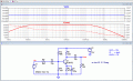
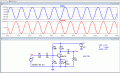
I started designing the common emitter amplifier with below specification.
Design Specification :
VCC = 12V
IC = 4mA
AVOL = 70

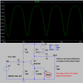
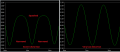
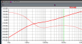
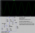
I have done some calculation to find all values needed in below circuit. When i run the simulation i found the gain of amplifier is 4.
I have expected the output voltage is 50mV*70 = 3.5Vpeak.
Could anyone figure the reason why the gain is only 4 ?

How do i can find close loop gain ?

Many thanks
1636827516177.png
1636827540641.png
 

Attachments

Thread Starter

mishra87

Joined Jan 17, 2016
1,034
Hello All,

Thanks for your suggestion.

After going through all your suggestions, i still have not found answer what i was trying to understand.
Please forgive if i am missing something here in my understanding...

1. Input = 50mVpeak, output = 200mV
How do i calculate the gain ?

2. All component value calculated for below..
VCC = 12V
IC = 4mA
AVOL = 70

3. I expect the output = AVOL * Input = 70*50mV = 3.5Vpeak.
 

Audioguru again

Joined Oct 21, 2019
6,647
Your simulation result is not distorting.
A transistor with no negative feedback and with a fairly high output level is not linear so it produces distortion.
My simulation of your circuit shows severe distortion. Here it is again with distortion and with very low distortion.
EDIT: I corrected the scale of the distorted signal:
 

Attachments

Last edited:

Jony130

Joined Feb 17, 2009
5,487
You did not provide enough room for the voltage to swing at the collector. Your DC voltage collector is Vc = 12V - 4mA * 437.5Ω = 10.2V.
Therefore 10.2 +/- 3.5V = 13.7V....6.7V how can the voltage at the collector be large than Vcc? And this is why you are getting distorted waveform.
Also, the C5 capacitor value is wrong (too small).
You forgot about hoe and the Early effect in your calculations.
What about the BJT parameter spread? And this is why your precise calculations are worthless.
 

Audioguru again

Joined Oct 21, 2019
6,647
Not only the collector voltage is too high but the emitter resistor value is so high that it throws away 1/3rd of the 12V supply voltage.
I agree that the wrong base biasing causes the collector DC voltage to be too high.
The collector voltage is far from clipping, the distortion is caused by having no negative feedback to reduce it, but negative feedback also reduces the gain.
 

Thread Starter

mishra87

Joined Jan 17, 2016
1,034
A transistor with no negative feedback and with a fairly high output level is not linear so it produces distortion.
My simulation of your circuit shows severe distortion. Here it is again with distortion and with very low distortion.
EDIT: I corrected the scale of the distorted signal:
Hello ,
Thanks.

This time your signal is looking good.
Could you please share LTspice to see the changes you have made.
You have attached only output waveform.

Cheers
 
Top