Facebook
 Google
 GitHub
 Linkedin
Hello
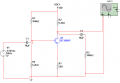
I have an assignment to do I am currently stuck in something. I need to use a BJT transistor BC109 to provide a voltage gain of 80. I have uploaded the requirements in PDF, I did task 1 and 2, I just need help in Task 3. how can I calculate the resistor value and capacitors in order to get a voltage gain of 80. also, can you provide an explanation of how the circuit works? for example, how can I change the frequency and why when changing the frequency the amplification changes.
Thanks
Attachments
-
 595.1 KB Views: 11
 -
504 KB Views: 12