Facebook
 Google
 GitHub
 Linkedin
Hi everyone,
I have been going around in circles on pages and forums for a couple days now, but just cannot seem to make any proggress with my problem.
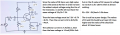
I have the below recuit (image attached).
I need to find R1.
Vcc = 22 V
R2 = 2 kΩ
Rc = 5 kΩ
RE = 5 kΩ
VBE = 0.7 V
b = 300
If anyone can help me, i would be grateful.
I have been going around in circles on pages and forums for a couple days now, but just cannot seem to make any proggress with my problem.
I have the below recuit (image attached).
I need to find R1.
Vcc = 22 V
R2 = 2 kΩ
Rc = 5 kΩ
RE = 5 kΩ
VBE = 0.7 V
b = 300
If anyone can help me, i would be grateful.
Attachments
-
 98.5 KB Views: 25
")