Facebook
 Google
 GitHub
 Linkedin
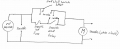
I've wired a circuit like the one at the top of the attached image. The wall switch is intended as an override on switch. I was not concerned about combing the wall switch leg with the relay leg because the source for both legs is the same 12/2 cable, and neither leg includes significantly capacitive or inductive components which would cause the voltage between the two legs to be out of phase.
I think I may have been wrong. I have observed 100VAC across the wall switch (between points A and B) when both the relay and switch are open. When the relay is closed and the switch is open, the voltage is 0 as expected.
Do you agree with my assessment that the voltages are out of phase between the two legs? I think something like this (https://www.desmos.com/calculator/gkqrbq72io) may be happening. However if that were the case, I would not expect the voltage to be 0 when the relay is closed.
Is this a problem?
The circuit at the bottom of the attached image seems like a good alternative. Unfortunately my local hardware store didn't have any 20A 3-way switches.