Combining LM2596 buck converter module with LM317 Linear Regulator

Ian0

Joined Aug 7, 2020
13,171
I was thinking along these lines, a small resistor value in series with the LM317 output before the feedback resistor which would need an increase in the necessary buck output voltage. Difference the voltage across the resistor with gain, then use a comparator to compare this to a pot wiper connected between +ve and ground. When this swings to the rail it would pull the transistor base high to turn it off….
. . . and then what happens? The output current is now below the threshold, so it turns back on again.
 

crutschow

Joined Mar 14, 2008
38,598
I was thinking along these lines, a small resistor value in series with the LM317 output before the feedback resistor which would need an increase in the necessary buck output voltage. Difference the voltage across the resistor with gain, then use a comparator to compare this to a pot wiper connected between +ve and ground. When this swings to the rail it would pull the transistor base high to turn it off….
Hoping this would work, or am I overthinking?
Sounds iffy.
What transistor?
Schematics are the language of electronics.
Post one of your idea.
 

panic mode

Joined Oct 10, 2011
5,116
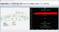
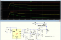
Here's a sim with LM2596. I increased R2 to 13.6k to allow the system to begin to regulate.
Output is set for 1A@12V.
i don't think that works. the whole point of SMPS pre-regulator is to produce voltage couple of volts higher than output maintained by linear regulator. it should track output voltage and make sure that voltage at Vin of the linear regulator (you marked it as V(hi_out)) is just 2.5-3V higher. and this circuit does not do that, since Vout is 12V, V(hi_out) should be 14.5-15V but it goes all the way up to V1.

so i tried it too and reduced output voltage, sure enough, V(hi_out) climbs to the supply voltage and makes no value that 317 regulator could see
1765426550192.png
 

panic mode

Joined Oct 10, 2011
5,116
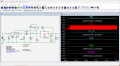
but something like this looks more like it. it should be V(hi_out) = Vz+Vout... result is higher for some reason but no time to evaluate right now.

1765427234367.png
 

eetech00

Joined Jun 8, 2013
4,711
i don't think that works. the whole point of SMPS pre-regulator is to produce voltage couple of volts higher than output maintained by linear regulator. it should track output voltage and make sure that voltage at Vin of the linear regulator (you marked it as V(hi_out)) is just 2.5-3V higher. and this circuit does not do that, since Vout is 12V, V(hi_out) should be 14.5-15V but it goes all the way up to V1.

so i tried it too and reduced output voltage, sure enough, V(hi_out) climbs to the supply voltage and makes no value that 317 regulator could see
View attachment 360333
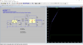
Why are you using 5V regulator and ideal PNP?
Change the LM2596 value to LM2596_ADJ so it uses the FB pin.
Also, use a 3906 PNP model.

1765428540107.png
 
Last edited:

crutschow

Joined Mar 14, 2008
38,598
result is higher for some reason but no time to evaluate right now.
The feed back phase is wrong.
The LM2596 adjusts the voltage until the FB pin voltage reaches its reference voltage.
The purpose of the transistor is to invert the feedback phase so a higher output voltage increases the switcher voltage by the same amount.
Look at my Post #13 sim.
 

Thread Starter

Jerry-Hat-Trick

Joined Aug 31, 2022
832
Would something like this work to include a variable current limit? ZCT1107 current sense amplifier across a small sense resistor, gain controlled with pot, if the output exceeds the Zener voltage it starts to add to the FB voltage so the LM2596 voltage would drop. Maybe a diode in series with the Zener so the FB voltage doesn't affect the sensing.
1765459662769.jpeg
 

crutschow

Joined Mar 14, 2008
38,598
Would something like this work to include a variable current limit?
The problem with that circuit is, the current limit value varies with the output voltage, which is not normally what you want.

Below is a circuit using a RR op amp that should work:
Pot U2 varies the current limit.
Schottky diode D2 provides a low voltage reference.

1765467574897.png
 
I’ve read through the discussion and the schematics shared so far — looks like some solid ideas!
Your approach using the LM358 for feedback adjustment is quite clever. Definitely something to watch out for is loop stability and accurate feedback voltage control.
Also, sometimes the internal feedback design of the LM2596 modules can affect modifications, so you might try adjusting the feedback resistor directly or using an adjustable regulator as a second stage.


Looking forward to seeing how your testing goes. Best of luck with your project!
 

MrAl

Joined Jun 17, 2014
13,738
I'm planning on using a 20V 3A supply to feed an LM2596 module (very cheap to buy) with the output going into an LM317 linear regulator to give me a very clean variable voltage output. I know there are other ways, but I have these components. I want to use the LM2596 to supply a voltage to the LM317 about 2 or 3 volts higher so the efficient buck converter does most of the work and the heat loss in the linear regulator is minimised.

I think if I use a 2 op amp LM358 powered by the 20V input I can somehow add the output of the LM317 (determined by a potentiometer) to 2 or 3V and difference this with the output voltage ofthe buck, by feeding this output to the FB pin of the buck I can automatically make the buck output 2 to 3V higher. The LM358 is not rail to rall but it does get close to the negative (ground) rail so the output can probably get down to the necessary 1.23V.

Is this possible? A schematic would be nice- I've searched and can find nothing like this.

Grateful for any ideas!
Hello there,

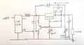
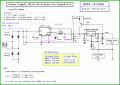
There have been some interesting suggestions here, this design is the traditional way of doing it (see attachment). This has been done in very large power supplies also so it's tried and proven.

This is the simplest design the more complicated ones we did a group project a long time ago and did a group buy for which we had a web ID and password for the parts list on Digikey. I am not sure if those credentials would still work today though, this is going back a whopping 20 years now (yeah I can't believe it has been so long now).

You can replace the zener with a few series diodes. It's meant to keep the output of the switcher always a little higher than the input to the linear regulator.

The version we did was a lot more complicated but there are a lot of parts in it too so it's a lot harder to build.

If you want current limiting it is easy to add but the complexity of the circuit depends on how perfect you want it to be. The simplest uses one transistor and a few resistors.

Also note the violet single point ground wiring, and the larger diode D1 cathode direct wiring. Also, the 1k resistor for the feedback lower resistor.
Most LM317's will work ok with a 220 Ohm resistor but you can go down to 120 Ohms if you like.
The transistor is a small one, like the 2N2222A or 2N4401 or similar.
 

Attachments

Last edited:

ronsimpson

Joined Oct 7, 2019
4,734
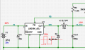
What is the purpose and function of diode D1?
The IC LM2596 is a switching regulator. In this case I wrote 20V for the input voltage and 10V for the output. At the spot called "SW" the wave form is about 50% duty cycle. It is at 20V for half the time and 0V at half the time. The average is 10V. L1 and Cout makes a filter that averages the waveform to get 10Vdc.
Inside the IC there is a switch that connects "IN" to "SW" to make 20V. When the switch is off the point "SW" drops to -0.7V which turns on D1.
SW is pulled up to near 20V by the IC and is held at -0.7 volts when the IC is open. (I said 0V but actually is one diode drop below ground)
1772671726180.png
 
Top