Colpitts oscillator parameters

Thread Starter

Antsy electron

Joined Dec 27, 2022
69
Salutations!!!
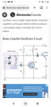
Hey guys , how are you doing ?.
Please refer to the image below . How do I find the values for the capacitors in such an oscillator ?. I mean , all of them , no just the ones in the tank . What's the criteria for the values of such capacitors , impedance based on desired frequency ?.
Thanks in advance.
 

Attachments

Papabravo

Joined Feb 24, 2006
21,159
It starts with a computation of capacitive reactance. This tells you about the ability to pass or block an AC signal based on frequency. Considering C3 & C4 you want a large reactance for DC and low frequencies, but you want a tiny reactance at the frequency of oscillation. Let us pick an example. Suppose the oscillator has a center frequency of 28.350 MHz. Let us further imagine that we want the reactance of C3 & C4 to be 100mΩ at that frequency. It goes like this:

\( X_C\;=\;(2\pi fC)^{-1} \) , which can be rearranged to give

\( C\;=\;(2\pi fX_C)^{-1}\;=\; (2*3.1415926*28.350e6*0.1)^{-1}\;\approx\;56nF \)

If you choose a different value of capacitive reactance, you will of course get a different result. What we do in most cases is pick the nearest value that we can purchase from stock and call it a day. In the case of E12 values for capacitors this would be a preferred value. If those are unavailable and we had to use 47nF then we could recompute the reactance at the frequency of interest to see if there is a significant difference. For coupling capacitors like C3 and C4 the actuals values will probably not be critical. Close is good enough.

The same considerations do not apply to capacitors C1 & C2. In terms of component selection there is a balance between what you can purchase and what you can fabricate. I'm thinking that fabricating inductors is more like likely that fabricating your own capacitors. I'm thinking that you would choose available capacitor values and then fabricate suitable inductors.
 

Thread Starter

Antsy electron

Joined Dec 27, 2022
69
Thanks a lot , that clarifies some doubts . Now , based on what I want the capacitor to be at an impedance of 100 ohms or any X amount of ohms ?. Does it has to match something ?.
 

Papabravo

Joined Feb 24, 2006
21,159
Thanks a lot , that clarifies some doubts . Now , based on what I want the capacitor to be at an impedance of 100 ohms or any X amount of ohms ?. Does it has to match something ?.
The loose requirement for C3 & C4 is that they block DC & low frequencies by having a large reactance at those frequencies. At the frequency of oscillation, you want them to have low reactance WITH RESPECT TO EVERYTHING ELSE in the signal path. There are no absolutes, and everything is relative to the surroundings. Because there are 6 orders of magnitude between 1 Hz and 28.350 MHz this is fairly easy to accomplish. You have some flexibility in this regard but the wrong choice of values for C3 and C4 might inhibit the operation of the oscillator with the circuit that you have shown.
 

Thread Starter

Antsy electron

Joined Dec 27, 2022
69
The loose requirement for C3 & C4 is that they block DC & low frequencies by having a large reactance at those frequencies. At the frequency of oscillation, you want them to have low reactance WITH RESPECT TO EVERYTHING ELSE in the signal path. There are no absolutes, and everything is relative to the surroundings. Because there are 6 orders of magnitude between 1 Hz and 28.350 MHz this is fairly easy to accomplish. You have some flexibility in this regard but the wrong choice of values for C3 and C4 might inhibit the operation of the oscillator with the circuit that you have shown.
Got it ... Thanks a lot Papabravo.
 

MisterBill2

Joined Jan 23, 2018
18,176
Most Collpits oscillators do not use such a basic circuit because it requires a tuning capacitor with the rotor isolated from ground. The circuit is a bit more complex as a result, but the math is simpler. And the frequency stability is much better.
 

MisterBill2

Joined Jan 23, 2018
18,176
Thanks a lot sir and excuse my ignorance . What is the rotor in an oscillator ??.
The two variable capacitors connected across the inductance mechanically consist of rotor plates and stator plates. I had presumed that you were familiar with the mechanical portion of the components. My mistake.. In a variable frequency oscillator some parts must be variable. Real circuits, unlike simulation circuits, tend to have physical components.
 

Thread Starter

Antsy electron

Joined Dec 27, 2022
69
The two variable capacitors connected across the inductance mechanically consist of rotor plates and stator plates. I had presumed that you were familiar with the mechanical portion of the components. My mistake.. In a variable frequency oscillator some parts must be variable. Real circuits, unlike simulation circuits, tend to have physical components.
Oh oh , ok ok , yes I know variable capacitors , I just didn't know that term for them. Thanks a lot sir.
 

MisterBill2

Joined Jan 23, 2018
18,176
Much radio equipment uses a different arrangement of the Colpitts circuit, where the frequency setting tuned circuit can have one end grounded, and the divider with two capacitors in series is coupled to the top of the LC tuner by a small capacitor. The claimed benefit is that the two capacitors in series have much larger values that shunt the transconductance of the active device.
Somebody should be able to copy and post the circuit found in many ARRL publications for the past 50 years.
 

Thread Starter

Antsy electron

Joined Dec 27, 2022
69
Much radio equipment uses a different arrangement of the Colpitts circuit, where the frequency setting tuned circuit can have one end grounded, and the divider with two capacitors in series is coupled to the top of the LC tuner by a small capacitor. The claimed benefit is that the two capacitors in series have much larger values that shunt the transconductance of the active device.
Somebody should be able to copy and post the circuit found in many ARRL publications for the past 50 years.
I will look for it . I am experimenting with oscillators , it's fascinating, I love when i see waves in the oscilloscope.
 

Thread Starter

Antsy electron

Joined Dec 27, 2022
69
Please refer to the attached picture . I replace capacitors and inductors multiple times in this oscillator and the oscilloscope continue to read the same frequency . I test d the oscilloscope with a signal generator and works perfectly. What can be wrong with this circuit ?.
 

Attachments

Thread Starter

Antsy electron

Joined Dec 27, 2022
69
Please see figure . I replace components in the tank circuit and still the oscilloscope continue reading the same frequency. I tested the oscilloscope with a signal generator and it was good. The circuit was made in a breadboard. Why could be this happening ??. Screenshot_20230306-125616.png
 

MrAl

Joined Jun 17, 2014
11,389
What frequency are you after and what components have you changed and to what values have you changed them to?
 
Top