Colpitts generator Pspice

Thread Starter

arek462

Joined Jun 28, 2016
15
Hello!

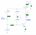
I tried simulate Colpitts Generator from Horowitz's book:

colpitts.png

I use free pspice version, so there isn't crystal:

colpitts_schematic.png

Unfortunately it doesn't work like generator:

colpitts_simulation.png

If any expert could help me make it work right, i will be very grateful.

Thank you!
 

Attachments

Bordodynov

Joined May 20, 2015
3,180
floating node ==> comon node C1 and C7 add resistor 1Gig.
IC = 1mA to speed up the calculation. It should .Tran 50m UIC. If you want to see the launch of the generator without these options, you must apply voltage leap. Note that I am one of the reduced capacities of up to 200 pF. There was no generation. Perhaps at a higher quality factor is generated. The lower quality factor, the faster the calculation.
.model 2n5485 njf(is=.25p alpha=1e-4 vk=80 vto=-2.0 vtotc=-3m beta=3.5m lambda=10m betatce=-.5 rd=10 rs=10 cgs=4p cgd=4p kf=3e-17 )
In your model, the transistor is too small capacity. See datasheet. Also, your transistor transconductance more than three times less. You may need to further reduce the capacity of the C3 (~100pF).
 
Last edited:

Thread Starter

arek462

Joined Jun 28, 2016
15
floating node ==> comon node C1 and C7 add resistor 1Gig.
IC = 1mA to speed up the calculation. It should .Tran 50m UIC. If you want to see the launch of the generator without these options, you must apply voltage leap. Note that I am one of the reduced capacities of up to 200 pF. There was no generation. Perhaps at a higher quality factor is generated. The lower quality factor, the faster the calculation.
You mean add parallel resistor 1G?
I've change C3 to 100p.
How add .Tran 50m UIC?
 
Last edited:

Bordodynov

Joined May 20, 2015
3,180
The resistor is attached to the ground with one pin (you can parallel capacitor).
Look in the job analysis. The option uic is valid for all Spice program (and for Pspice, ORCAD)
I corrected my previous post!
 
Last edited:

Thread Starter

arek462

Joined Jun 28, 2016
15
Thank you.

I added resistor and the floating node problem is gone. Howewer, circuit still doesn't work like i expected. Please help

Node.png
 

Bordodynov

Joined May 20, 2015
3,180
Just give me image of a circuit. Without waveforms. So that I can better see your circuit. Resistor correct. On waveform output power node. I want to be sure that in the zero voltage momet time zero and then changed to 24 volts.
You may need to increase the accuracy of the calculation. Make reltol=10u. I did that when counting crystal oscillators. and I used Pspice4.
 
Last edited:

Thread Starter

arek462

Joined Jun 28, 2016
15
Just give me image of a circuit. Without waveforms. So that I can better see your circuit. Resistor correct. On waveform output power node. I want to be sure that in the zero voltage momet time zero and then changed to 24 volts.
Now i know what you meant.

So in the beginning voltage must be 0 and then after some short time 24V.
Do you how to set it?

Błąd.png
 

Bordodynov

Joined May 20, 2015
3,180
Yes, you understood me correctly. I usually use front enable 1 microsecond, but it is possible and faster. This gives the initial impetus fluctuations. And further. Do not use the default transistor. In the second scheme, I took the same model that you take.
 

Thread Starter

arek462

Joined Jun 28, 2016
15
Yes, you understood me correctly. I usually use front enable 1 microsecond, but it is possible and faster. This gives the initial impetus fluctuations. And further. Do not use the default transistor. In the second scheme, I took the same model that you take.
So, what do you advice?

Now i use this transistor .model 2n5485 njf(is=.25p alpha=1e-4 vk=80 vto=-2.0 vtotc=-3m beta=3.5m lambda=10m betatce=-.5 rd=10 rs=10 cgs=4p cgd=4p kf=3e-17 ).

What should i do to get the same waveform like you in your first post?

http://forum.allaboutcircuits.com/attachments/draft300_plot-png.108432/
 

Bordodynov

Joined May 20, 2015
3,180
You can simulate a text file. ORCAD allows you to do it.
* D:\Program Files\LTC\LTspiceIV\Draft302.asc
r1 g 0 1meg
j1 out g 0 j2n5485
r2 VCC out 4.7k
c1 out n002 1000pf
c2 out 0 1000pf
c3 0 g 200pf
l1 p001 g 0.159154943091895
c4 p002 p001 1.59154943091895e-013
r3 n002 p002 100
c5 n002 g 2e-012
v1 VCC 0 pwl(0 0 1us 24v)
r4 n002 0 1g
.model j2n5485 njf(beta=1.039m betatce=-500m rd=1 rs=1 lambda=4.25m vto=-2.5
+ vtotc=-2.5m is=33.57f isr=322.4f n=1 nr=2 xti=3 alpha=311.7 vk=243.6
+ cgd=1.6p m=362.2m pb=1 fc=500m cgs=2.414p kf=7.832e-003f af=1)
.tran 0 50m 0 .1u
.option reltol=1u
.probe V(out) V(g) V(vcc)
.end
 

Attachments

Bordodynov

Joined May 20, 2015
3,180
This file is for Pspice. ORCAD Pspice uses. Before the calculation of the graphical design turns a text file. The text file and is used for the calculation. I used ORCAD9.1 and ORCAD9.2. They allow you to count text files, as well as other SPICE-program. I did it. Start my file!
 
Top