 Facebook
 Google
 GitHub
 Linkedin
You know what? ... I like this circuit so much that I think I'm actually going to build it ... and I'll be using it to control the speed of a Milwawkee 5625-20 router, whose original controller works just fine (in fact, it actually works beautifully), but its lowest speed is too high for the things that I want to do with it... like cutting soft plastics that melt at the 10,000 rpm that it delivers at its lowest speed setting.
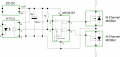
Here's my first attempt at a sim of the original circuit. But since this is a closed-loop concept, I have no idea as to how to sim the revs of a real motor. So what I did was include a variable frequency source (shown at the left), that simulates the encoder's output of a motor varying its speed, and fed it to the circuit on the right. I also adjusted some of the resistors to more standard, commercially available values.

From what I'm seeing, the circuit seems to be working fine. What I have to do now is add a couple of back-to-back n-Fets to switch AC instead of just DC, plus an opto-isolated driver using a floating-type power supply. I'll be back later with said circuits, plus a few tweaks. Including how I plan to use the magnetic encoder already installed in the router. Who knows... after I'm done it might be a circuit worthy of being included in the finished projects forum.
I've started a new thread inviting the previous participants, to avoid hijacking the original one.
@Bernard, @MaxHeadRoom, @pratto, @KeepItSimpleStupid, @ebeowulf17
Here's my first attempt at a sim of the original circuit. But since this is a closed-loop concept, I have no idea as to how to sim the revs of a real motor. So what I did was include a variable frequency source (shown at the left), that simulates the encoder's output of a motor varying its speed, and fed it to the circuit on the right. I also adjusted some of the resistors to more standard, commercially available values.
From what I'm seeing, the circuit seems to be working fine. What I have to do now is add a couple of back-to-back n-Fets to switch AC instead of just DC, plus an opto-isolated driver using a floating-type power supply. I'll be back later with said circuits, plus a few tweaks. Including how I plan to use the magnetic encoder already installed in the router. Who knows... after I'm done it might be a circuit worthy of being included in the finished projects forum.
I've started a new thread inviting the previous participants, to avoid hijacking the original one.
@Bernard, @MaxHeadRoom, @pratto, @KeepItSimpleStupid, @ebeowulf17
Attachments
-
5.6 KB Views: 4
Last edited:

")


