Facebook
 Google
 GitHub
 Linkedin
Hello everyone,
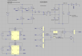
I've got an assignment to design LLC converter and I would like to control it with a closed feedback loop.
The resonant circuit works fine. I designed the converter so that it has constant 100 V output, maximum output current is 10 A.
My assumption is that the input voltage can vary by 10% from 292.5 to 357.5 V DC - normal is 325 V (this is the rectified 230V AC).
The gain of the resonant circuit can compensate the variation of input voltage. It can be achieved by changing the control frequency in a specified range (86 kHz to 205 kHz - resonant frequency is 150 kHz).
The parameters of the converter:
Input voltage: 325 V DC (rectified and filtered 230 AC)
Maximum output power: 1 kW (100 V, 10 A)
Resonant frequency: 150 kHz
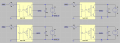
I just completed simulating the converter with closed control loop that has an output constant frequency, variable duty cycle PWM. That was just an attempt to see if I can do it (im new to this stuff) and to see how the circuit behaves.

Now I would like to try designing a control loop that has variable frequency PWM as an output. That was my initial assumption to control it that way. Unfortunately I don't know how to it in LTspice I looked up on the web as much as I could and came up with few ideas:
- using LTC 6992 that has ability to change frequency based on resistor aplied to Rset pin,
- using "modulate" block from LTspice library (but as far as I know it has sine wave as an output),
- using timer 555 to generate variable frequency signal.
Is there a way to do it? Can you give me some clues or resources to read/watch that could help?
I could use some designed for LLC convertes integrated circuits but I kind of have to do it based on discrete elements (simmilar to what I did on the picture above).
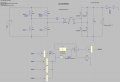
Also I do have a question:
- How to prevent mosfet source current (Is(M3) - red waveform) from these spikes, when the bridge output voltage (blue waveform) goes up?

Thank you for your time!
I've got an assignment to design LLC converter and I would like to control it with a closed feedback loop.
The resonant circuit works fine. I designed the converter so that it has constant 100 V output, maximum output current is 10 A.
My assumption is that the input voltage can vary by 10% from 292.5 to 357.5 V DC - normal is 325 V (this is the rectified 230V AC).
The gain of the resonant circuit can compensate the variation of input voltage. It can be achieved by changing the control frequency in a specified range (86 kHz to 205 kHz - resonant frequency is 150 kHz).
The parameters of the converter:
Input voltage: 325 V DC (rectified and filtered 230 AC)
Maximum output power: 1 kW (100 V, 10 A)
Resonant frequency: 150 kHz
I just completed simulating the converter with closed control loop that has an output constant frequency, variable duty cycle PWM. That was just an attempt to see if I can do it (im new to this stuff) and to see how the circuit behaves.
Now I would like to try designing a control loop that has variable frequency PWM as an output. That was my initial assumption to control it that way. Unfortunately I don't know how to it in LTspice
I looked up on the web as much as I could and came up with few ideas:- using LTC 6992 that has ability to change frequency based on resistor aplied to Rset pin,
- using "modulate" block from LTspice library (but as far as I know it has sine wave as an output),
- using timer 555 to generate variable frequency signal.
Is there a way to do it? Can you give me some clues or resources to read/watch that could help?
I could use some designed for LLC convertes integrated circuits but I kind of have to do it based on discrete elements (simmilar to what I did on the picture above).
Also I do have a question:
- How to prevent mosfet source current (Is(M3) - red waveform) from these spikes, when the bridge output voltage (blue waveform) goes up?
Thank you for your time!
Attachments
-
 75.6 KB Views: 158