Clock 24 design Help

Thread Starter

ThiagoBlys

Joined May 24, 2022
4
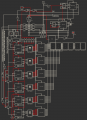
Well... I'm new here and it's the first time I've been posting things on forums or something like that (I don't even know if I have the morals for it); But anyway, I would like to show, here, a small project that I did in an Integrated Circuit simulator... A Clock... Well I'm not a professional in CI(IC), but I started a few months ago (less than 5 months).
 

Attachments

dl324

Joined Mar 30, 2015
16,839
Welcome to AAC!

Your schematic is unreadable. The connection dots on the inputs/outputs are distracting and the unnecessary wire jogs and crossings add to the unreadability.

For clocks, I find schematics are "easier" to read when you have the data flow right to left:
1653445946197.png
 

AnalogKid

Joined Aug 1, 2013
10,986
The text is so small that I can't see what the chips are. Please post a larger image.

Also, why are five non-inverting buffers connected in parallel?

ak
 

dl324

Joined Mar 30, 2015
16,839
Also, why are five non-inverting buffers connected in parallel?
He appears to be trying to bus the signals by routing wires on top of each other and not labeling them where they enter/leave the bus.

Being able to read the text still doesn't help:
1653487608534.png
 

Thread Starter

ThiagoBlys

Joined May 24, 2022
4
The text is so small that I can't see what the chips are. Please post a larger image.

Also, why are five non-inverting buffers connected in parallel?

ak
The text is so small that I can't see what the chips are. Please post a larger image.

Also, why are five non-inverting buffers connected in parallel?

ak
The ANDs are resetting the "Click Switch 1/4"; I turned the switch on NOT to HIGH on the Buffers and reset the "Click Switch 1/4" if I turn off the switch. As the file import is giving errors, I redid and made the space shorter, but I still couldn't fix the error. And yes, they are all separated for each "Click Switch 1/4", so the wires of each Buffer are on top of each other in favor of short space.
 

Thread Starter

ThiagoBlys

Joined May 24, 2022
4
Welcome to AAC!

Your schematic is unreadable. The connection dots on the inputs/outputs are distracting and the unnecessary wire jogs and crossings add to the unreadability.

For clocks, I find schematics are "easier" to read when you have the data flow right to left:
View attachment 267945
Hi! Thanks for some suggestions! Yes, there are some unnecessary things. I was making a copy of a watch that my nephew owns, his watch has some functions and animations that I challenged myself to do the same (to see, something I had no idea how to start, how it would get out of my mind). As I'm a beginner and I'm just Hobbie, I decided to do it the way the app provides (delays) and as far as I can go with what I know, even if there is some unnecessary logic. :)
 
Top