Clipping on CE ampflifier

BobTPH

Joined Jun 5, 2013
11,517
Everyone seems to be laser focused on the load impedance. While this explains why he is getting no gain out of the circuit, it does not explain the clipping that he is seeing.

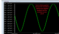
It's my belief that if you remove the load entirely you will still see the clipping because it is do to the amplifier being overdriven by a 100 mV input signal.

Also, a signal of 100 mV is considerably larger than the thermal voltage, which you should stay below if you want the small-signal model to remain reasonably linear.
The gain of the unloaded amp is about 2 (1300/667), so the output with no load should be roughly 200 mV. I don’t see that clipping.

Now add an 8 Ohm load and see what happens.
 

WBahn

Joined Mar 31, 2012
32,853
The gain of the unloaded amp is about 2 (1300/667), so the output with no load should be roughly 200 mV. I don’t see that clipping.

Now add an 8 Ohm load and see what happens.
The emitter resistor is bypassed with a capacitor that makes it go away at signal frequencies. Thus the gain is determined by the small-signal emitter resistance. When this is the case, the gain is given by the ratio of the voltage dropped across collector resistor at DC bias to the thermal voltage, which in this case puts the gain in the 150 to 160 range.
 

WBahn

Joined Mar 31, 2012
32,853
I took his .asc file and deleted the load and output capacitor and added a label for the collector node and ran his simulation. Here's the result:

1666382667511.png

Clearly the gain is a LOT more than 2.

I backed off the signal amplitude to 10 mV and got this:

1666382759986.png

Looks pretty clean, though there may be distortion that's not obvious to me.

The peak-to-peak voltage is (9.58 V - 7.12 V) = 2.46 V, so the amplitude if 1.23 V, yielding a gain of 123.

If the input impedance is 900 Ω and the source impedance is 100 Ω. that means that we are losing 10% in the input coupling, which bumps the transistor gain up to about 137.

The DC bias current is about 3 mA, making the voltage across Rc about 3.9 V. Dividing that by a thermal voltage of 26 mV yields an expected gain of 150, which is pretty close. The actual DC bias voltage drop across the collector resistor is about 3.5 V, which when divided by the thermal voltage yields an expected gain of 135. It doesn't get much closer than that.
 

Audioguru again

Joined Oct 21, 2019
6,826
The original circuit was very overloaded and had extreme distortion but had no voltage gain.
Usually an 8 ohm speaker is driven by a power amplifier circuit at audio frequencies.
I fixed it but it is not a power amplifier driving a speaker with audio frequencies.

Didn't the lecturer say, "Design an audio power amplifier"?
 

Attachments

WBahn

Joined Mar 31, 2012
32,853
Didn't the lecturer say, "Design an audio power amplifier"?
I don't see any hint of what the assignment actually was. The fact that the frequency is so far above the audio range suggests that it is NOT an audio amplifier of any kind. That the frequency isn't RF doesn't say much at all -- the world has lots of things that exist between audio and radio frequencies. Plus, there's a good chance that the assignment is completely contrived as far as specs go. Similarly, that two of the three capacitors place the bandpass well above the audio range. The only thing that suggests an audio amplifier is the impedance of the load, and that may or may not be coincidental.

@jclfc Could you please provide the actual assignment so that none of us inadvertently lead you down a rabbit hole?
 

BobTPH

Joined Jun 5, 2013
11,517
The emitter resistor is bypassed with a capacitor that makes it go away at signal frequencies. Thus the gain is determined by the small-signal emitter resistance. When this is the case, the gain is given by the ratio of the voltage dropped across collector resistor at DC bias to the thermal voltage, which in this case puts the gain in the 150 to 160 range.
Yep, I missed that.
 
Top