Avoid clipping by op amp filtering with +/- 6V power supply

Thread Starter

PeteHL

Joined Dec 17, 2014
562
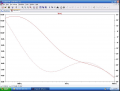
The op amps are TL072 so from the spec sheet for this op amp I estimate that the greatest peak output voltage Vom is about +/- 4V. Attached is the circuit schematic and decibels versus frequency of the circuit from a simulation with LTspice. My question is this. If the output of a CD player that equals 3.5 VRMS is at input to the circuit, will this result in voltage clipping by the circuit? If yes, then how much voltage attenuation of the the output voltage of the CD player is required to avoid clipping?

Thanks for your feedback- Pete

FIG_K-16.1.JPGPLOT_FIG_K-16.1.JPG
 

Ian0

Joined Aug 7, 2020
13,097
Yes, because 3.5V rms is already greater than 4V peak.

I think 3.5V rms is probably wrong for the output of a CD player.

If you assume the pink noise approximation, then a third of the power will be between 20Hz and 200Hz, and you have a gain of 8. but the amount of attenuation will depend on the type of music you listen to. Your power amplifier will have a volume control on the input, which you can use to provide as little or as much attenuation that you need.

4V peak is more than enough to clip the output of a power amplifier. Most require 0dBm (775mV rms or 1.1V peak)

A loudspeaker that needs 20dB of response correction isn't a good loudspeaker. 20dB of extra gain will probably drive it beyond its linear cone excursion limit.
 
Last edited:

Thread Starter

PeteHL

Joined Dec 17, 2014
562
Yes, because 3.5V rms is already greater than 4V peak.

I think 3.5V rms is probably wrong for the output of a CD player.

If you assume the pink noise approximation, then a third of the power will be between 20Hz and 200Hz, and you have a gain of 8. but the amount of attenuation will depend on the type of music you listen to. Your power amplifier will have a volume control on the input, which you can use to provide as little or as much attenuation that you need.

4V peak is more than enough to clip the output of a power amplifier. Most require 0dBm (775mV rms or 1.1V peak)

A loudspeaker that needs 20dB of response correction isn't a good loudspeaker. 20dB of extra gain will probably drive it beyond its linear cone excursion limit.
The 3.5Vrms is distributed throughout the audio frequency spectrum and that is what causes me to be unable to understand whether or not that signal level would cause clipping.

According to Stereophile , the range of output voltage (RMS) of cd players is 2.2V to 3.5V, and in a few cases even higher.

A voltage gain of 5.62 is 15 dB.

I don't mind terribly, but you are raising issues that are outside of what I'm asking about.

Regards,
Pete
 

Ian0

Joined Aug 7, 2020
13,097
How the 3.5V is distributed through the audio spectrum depends on the type of music you are playing. Assuming that it is all in the 20Hz to 200Hz decade won't be far wrong and will allow a little headroom. Occasionally it will ALL be at a single frequency, and that frequency is likely to be a bass guitar note, or in a single event such a drum beat
My experience of CD players is that manufacturers like to run the D/A and output amplifier of the same 5V supply in order to save money on extra power supplies, so you will probably get 4.5V peak-to-peak.
 

ericgibbs

Joined Jan 29, 2010
21,391
Hi Pete,
This is the Fourier response for your amp with a3.5Vrms input.
BTW: the Bode response of your amp is very poor over that range of frequencies.
E
EG57_ 1565.png
 

ericgibbs

Joined Jan 29, 2010
21,391
Hi Pete,
A 10k R9 will give a 6dB reduction, I would consider R9 could be a 50k preset resistor, that would allow some adjustment of the overall gain,
E
EG57_ 1566.png
 

Thread Starter

PeteHL

Joined Dec 17, 2014
562
Hi Pete,
A 10k R9 will give a 6dB reduction, I would consider R9 could be a 50k preset resistor, that would allow some adjustment of the overall gain,
E
View attachment 317898
Thanks for simulating this. The problem with adjustable gain I think is that clipping if it does occur might not be easily heard and therefore creating no basis for setting attenuation.
 

Thread Starter

PeteHL

Joined Dec 17, 2014
562
A loudspeaker that needs 20dB of response correction isn't a good loudspeaker. 20dB of extra gain will probably drive it beyond its linear cone excursion limit.
The Linkwitz Transform circuit provides 18 dB of boost to a loudspeaker system to extend its bass response. It's boost occurs over 1.5 octaves. My circuit is producing 15 dB of boost over about 4 octaves.

https://linkwitzlab.com/filters.htm#9
 

LowQCab

Joined Nov 6, 2012
5,101
""............ is that clipping, if it does occur, might not be easily heard, .......... ""
.
If You can't hear the Clipping, then the Clipping is irrelevant.

Unless You are trying to avoid installing Trim-Pots for setting interstage-Gain-Levels
this shouldn't be too much of a problem.

~15db of Gain, is a Voltage-Gain of roughly 5.62X which will definitely cause HARD CLIPPING,
that is, IF the CD-Player will actually put out anything close to the maximum Voltage that it is capable of,
which is an extremely unlikely scenario.
The CD-Player is more than likely to only produce about half of it's Maximum-Voltage-Output on
some unusually HOT-PEAKS found on some poorly Mastered CD.

The usual Supply-Voltage-Range for a Pre-Amp / EQ is usually around Plus and Minus ~15-Volts,
they use that much Voltage for a reason,
they don't ever want the Signal to get anywhere near the Supply-Rails.
If You want to use ~6-Volt-Supplies,
You will have to be much more meticulous about setting interstage-Gain-Levels
to insure that You stay out of Clipping under every conceivable circumstance.

The only way to Guarantee no Clipping is with an Oscilloscope, a Test-Tone-CD, and Trim-Pots.
"Guessing" at the Output of the CD-Player is folly.
.
.
.
 

ericgibbs

Joined Jan 29, 2010
21,391
In that simulation, the signal source is 1 kHz is that correct? And then you write that the bode response is poor because of the high level of harmonics?
Hi Pete.
No, I am not saying that because of the Fourier plot, it is based on the poor Bode plot response you posted in your opening post.

E
 

Attachments

Audioguru again

Joined Oct 21, 2019
6,826
In 1964 I bought a pair of Acoustic Research AR4 2-way (8" woofer in a large sealed enclosure) speakers because they sounded almost the same as their expensive AR-3 3-way (12" woofer) speaker (said to be the best-sounding speaker at any price).
My speakers had a flat frequency response down to 55Hz but I wanted deeper bass so I built a bass-boost circuit similar to the Linkwitz circuit but with 12dB boost at 30Hz. All my friends said it sounded and felt like there was a sub-woofer hidden somewhere.
The flexy wire connecting the voicecoil on one woofer broke 25 years later.
 

Thread Starter

PeteHL

Joined Dec 17, 2014
562
The usual Supply-Voltage-Range for a Pre-Amp / EQ is usually around Plus and Minus ~15-Volts,
they use that much Voltage for a reason,
they don't ever want the Signal to get anywhere near the Supply-Rails.
The reason for the power supply voltages of +/ - 6V is that this is for a system powered by a 12V battery.
 
Last edited:

Thread Starter

PeteHL

Joined Dec 17, 2014
562
Comment from Mr. LInkwitz ". . . provided the driver has adequate volume displacement capability and power handling."
Yes, that actually might be something to consider with my speaker but at this point the easiest thing for me to do is just try it. Calculating whether not this would compromise the drivers of my speaker would be a headache.
 

Thread Starter

PeteHL

Joined Dec 17, 2014
562
Playing a recording of pink noise with a CD player, I measured the output level of the player equal to 130 mVRMS +/- 10 mV with my HP 3478A multimeter. Connecting the output of the CD player to the input of my filtering circuit with the power supply changed to +/ - 15VDC, and connecting the output of my circuit to a channel input of my oscilloscope, the peak voltage of the trace on the screen doesn't exceed 1.25V. Using the conservative output level of a CD player equal to 2000 mVRMS, I calculated input attenuation required to prevent clipping at the output of my circuit by limiting output peak voltage to 4V.

attenuation = (test input Vrms/ 2000 Vrms) X (4v/ measured max. Vpeak)

attenuation = (130 mV/ 2000 mV) X (4V/ 1.25V) = 0.21

From this I concluded that I should attenuate the input signal from a CD player by about 1/5th to prevent clipping in my filtering circuit the schematic of which is attached to my first post.

Would you agree that this is reasonable?

-Pete
 

LowQCab

Joined Nov 6, 2012
5,101
A "Pink-Noise-CD" may not necessarily be recorded at the maximum "Digital-Volume" that
is possible to be encoded on to a CD.

There are CDs encoded to specifically test Output-Levels,
this would be the "proper" way to test your setup.

And, now that You have a "general idea" of what the levels "probably" or "should-be" close to,
You can now safely go back to lower Supply-Rail-Voltages.

There is no reason to test at any Frequency other that the Peak-Frequency of your Filter,
which appears to be near ~75Hz, according to your supplied Graphs,
( which is way too high for my tastes, it needs to be around ~25 to ~30Hz,
if your Speakers can reliably reproduce those Frequencies without severe-distortion or damage ).

There "may" be documented "standards" for "recommended" Maximum or "Nominal" Output-Levels,
but I personally have no-clue whether these standards even exist, or
are rigorously adhered-to by any particular CD-Player-manufacturer.
.
.
.
 
Top