Class AB - CS Amplifier - Current Flows

Thread Starter

elec_eng_55

Joined May 13, 2018
214
Hi:

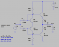
I am trying to understand the dc current flow in a Class AB Comlementary-Symmetry amplifier circuit.
See attachments.

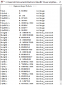
At 50.55mA of dc bias current flows into point A and splits three ways. 322.79uA flows to the Q3 base, 205.03uA flows into
the Q1 base and 50.02mA flows into the Q3 collector. I want to understand why the current splits in these proportions and
how you would calculate mathematically how the current will split.

The same situation applies to point B. -49.95mA flows into point B from the Q4 collector, -247.02uA flows into point B from the
Q2 base, -399.29uA flows into point B from the Q4 base, and then 50.59mA flows from point B to ground.

Thanks,

David
 

Attachments

Jony130

Joined Feb 17, 2009
5,593

Thread Starter

elec_eng_55

Joined May 13, 2018
214

Jony130

Joined Feb 17, 2009
5,593
Hmm, If I did not make any mistake it will be something like this.

The voltage difference between A and B point is equal to :

Vab = Vt*ln((I_Rb1 - Ib1)/Is3) + Vt*ln((I_Rb1 - Ib1)/Is4) = Vt*ln(Ie1/Ise1) + (Re1 + Re2)*Ie + Vt*ln(Ie2/Ise2)

And for point A we have

(Vcc - Vc)/Rb1 - Ie3 -Ib1 = 0

And for point B

Ie3 + Ib2 = VB/Rb2

But I do not see a point of doing such a calculation. Because you will never know "Is" current and temperature plays a big role in this also.
 

crutschow

Joined Mar 14, 2008
38,322
The base current in a transistor is equal to the collector current divided by the current gain (Beta or hFE) of the transistor.
The current gain of a transistor can vary widely (typically around 3:1) from unit to unit, so the actual base current will depend on the particular transistor in the circuit.

The emitter current is the sum of the base and collector currents, of course.
 

Jony130

Joined Feb 17, 2009
5,593
To give you the idea of what is going on in this circuit at DC and because your circuit is symmetrical we can try to analyze this simplified circuit (upper half):

10.png
I hope that now you see why Ic2 is lower than Ic1. The collector current is determined by the Vbe voltage. Hence in this circuit Ic1 = Ic2 only when Vbe1 = Vbe2. But in this circuit Ic1 < Ic2 because Vbe1 > Vbe2. I hope you see this ( Vbe1 = Vbe2 + Ie*RE ).

And the math:
Let us assumed that Vcc/2 = 0V

We have

(Vcc - Vbe1)/R1 = Ic1 + Ib1 + Ib2

(Vcc - Vbe1)/R1 = Ic1 + Ic1/β1 + Ic2/β2 ---> Ic1 = (β1/β1 + 1)*[ ((Vcc - Vbe1)/R1) - (Ic2/β2) ]

Knowing Ic1 we can find Vbe1

Vbe1 = Vt * ln(Ic1/Is1)

We also know that

V_RE = Vbe1 - Vbe2 = Vt*ln(Ic1/Ic2)

Ie2 = Ic2*(β +1)/β = Ic2* (1 + 1/β2)

We have

Ic2 = (Vt/(1 + 1/β2)*RE) * ln(Ic1/Ic2)

Can you solve this type of an equation and find Ic1 and Ic2 ? For example for Vcc = 5V; R1 = 4.4kΩ and RE = 35Ω for β1 = β2 = 100 and Is1 = Is2 = 1E-13 ?
 
Last edited:

newbie2019

Joined Apr 5, 2019
95
To give you the idea of what is going on in this circuit at DC and because your circuit is symmetrical we can try to analyze this simplified circuit (upper half):

View attachment 167698
I hope that now you see why Ic2 is lower than Ic1. The collector current is determined by the Vbe voltage. Hence in this circuit Ic1 = Ic2 only when Vbe1 = Vbe2. But in this circuit Ic1 < Ic2 because Vbe1 > Vbe2. I hope you see this ( Vbe1 = Vbe2 + Ie*RE ).

And the math:
Let us assumed that Vcc/2 = 0V


We have

(Vcc - Vbe1)/R1 = Ic1 + Ib1 + Ib2

(Vcc - Vbe1)/R1 = Ic1 + Ic1/β1 + Ic2/β2 ---> Ic1 = (β1/β1 + 1)*[ ((Vcc - Vbe1)/R1) - (Ic2/β2) ]

Knowing Ic1 we can find Vbe1

Vbe1 = Vt * ln(Ic1/Is1)

We also know that

V_RE = Vbe1 - Vbe2 = Vt*ln(Ic1/Ic2)

Ie2 = Ic2*(β +1)/β = Ic2* (1 + 1/β2)

We have

Ic2 = (Vt/(1 + 1/β2)*RE) * ln(Ic1/Ic2)

Can you solve this type of an equation and find Ic1 and Ic2 ? For example for Vcc = 5V; R1 = 4.4kΩ and RE = 35Ω for β1 = β2 = 100 and Is1 = Is2 = 1E-13 ?
Hi

I have been looking at your formula Ic2 = (Vt/(1 + 1/β2)*RE) * ln(Ic1/Ic2) but Ic2 is on both sides of the equation. How do you compute vbe2? Since I am new to this (student), I am not sure where to find Vt and Is on a datasheet.

thx
 
Last edited:

Jony130

Joined Feb 17, 2009
5,593
I have been looking at your formula Ic2 = (Vt/(1 + 1/β2)*RE) * ln(Ic1/Ic2) but Ic2 is on both sides of the equation
Yes, I know. You could calculate everything but in this circuit, the simplest BJT model (Ic = β*Ib and constant Vbe) does not work. You are forced to use a Shockley equation for a BJT's, but the most significant problem is that BJTs parameters vary a lot -- even within a batch.
And we do not know the most of BJT parameters to be able to start the calculations. And also, exact calculations also involve solving a nonlinear equation by iteration or LambertW.

See the example here:
https://forum.allaboutcircuits.com/threads/trying-to-understand-current-flow.156067/


how do you compute vbe2?
From Shockley equation. Did you ever heard about it?

I am not sure where to find Vt and Is on a datasheet.
Well

Vt is aThermal voltage.

https://en.wikipedia.org/wiki/Boltzmann_constant#Role_in_semiconductor_physics:_the_thermal_voltage

At 25°C it is equal to 25.69258mV and this is why in hand calculations we usaly use the 25mV or 26mV.


As for the "Is" current first read this if you are not familary with Shockley equation.

https://forum.allaboutcircuits.com/blog/fun-with-the-diode-equation.589/#comment-1283

And you will not find "Is" current in the datasheet. Because of the fact that the "Is" current not constant and highly dependent on device temperature additional it also varies a lot from device to device This is why "exact" calculations of a BJT circuits are almost impossible to make.

But if you whant "Is" value the for small signal BJTs, expect it to be in the area of about 10^-14 A ... 10^-15 A .

Or you can calculate it.

If you know the Vbe1 voltage for a given collector current Ic1 you can solve for "Is":

Isat = Ic1 * exp ( -Vbe1/Vt )

Or if you know the Vbe1 value at some specified collector current Ic1 , then you can compute Vbex for any other collector current (Icx) without knowing the "Is" current:

Vbex = Vbe1 + Vt * ln( Ic1/Icx)

And remember that the Vbe will go up 60mV or down for every upward /down change in Ic by a factor of ten (decade change).

For example if Vbe is 0.62V for Ic = 1mA if now Ic increases to 10mA the Vbe voltage will rise to 0.62V + 60mV = 0.68V.
Or if Ic current drops to 0.1mA the Vbe will also drop to 0.56V.
 
Top