Class AB Push-Pull Amplifier - Total Current Drain (On Supply)

Thread Starter

elec_eng_55

Joined May 13, 2018
214
Hi:

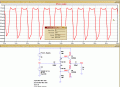
I am trying to figure out the total current drain. LTSpice says 140mA and Paul Malvino's
electronic worksheet says 417 mA (http://malvino.com/).

I would think that the formula should be Idrain = Ibias + Iavg + ICQ.

Ibias = (Vcc - 1.4 ) / (Rb1 + Rb2) = (20V - 1.4V) / (180Ω + 180Ω) = 50mA

Isat = Vceq / RL = 10V / 10Ω = 1A

Iavg = Isat / π = 1A / 3.14 = 318mA

Given that ICQ = Ibias as long as diodes and transistors are matched.

∴ Idrain = 50mA + 50mA + 318mA = 418mA

but why is LTS different?

David
 

Attachments

Thread Starter

elec_eng_55

Joined May 13, 2018
214
No, the collector currents, use the LTS plots to check the currents.

Look at this plot with the signal input at 0V.
This what your calculations are showing ie: the quiescent condition
This should not be like trying to pull teeth.

So the 140mA is the "Operating Point" or "Quiescent Point" at 140 mA.

140mA - 49mA bias current = 91mA

Where does LTS get the collector current of 91mA?
 

ericgibbs

Joined Jan 29, 2010
18,766
The current in the bias network is ~51mA
The Current in Q1 and Q2 is the same current ie: 89mA
89mA + 51mA = 140mA

I don't see why you are having a problem, these are your figures.

Not sure what the teeth pulling comment is supposed to mean.??

AA1 29-Sep-18 19.48.gif
 

Thread Starter

elec_eng_55

Joined May 13, 2018
214
The current in the bias network is ~51mA
The Current in Q1 and Q2 is the same current ie: 89mA
89mA + 51mA = 140mA

I don't see why you are having a problem, these are your figures.

Not sure what the teeth pulling comment is supposed to mean.??

View attachment 160684
I am trying to figure out how LTS arrives at 89mA collector current. I get where
the 51mA comes from. I like to understand things to the point that I can calculate
values and use LTS as a means of confirming my values.
 
Last edited:

ericgibbs

Joined Jan 29, 2010
18,766
Consider Q2. [ quiescent]

Ic= 89mA and Ib= 49uA
That a gain of ~180
Its a Class 'A' Amp so the Iq = ~90mA
Where do you think the 89mA is coming from.?
 

Jony130

Joined Feb 17, 2009
5,487
You have no clue what you are talking about!
LOL I think the other way around is true.
I why you "assaulting" people that are trying to help you?

Where does LTS get the collector current of 91mA?
Because the D1 and D2 diodes are not matched with the BJT's

In LTspice the D1 diode current is equal around of 50mA and the Vd1 ≈ 791mV

So, the Q1 collector current will be in the range of about Ic1 ≈ 1E-14A * e^(791mV/25mV) ≈ 163mA
But LTspice shows around 90mA because my simplified calculations do not include Q1 internal base resistance (20Ω) and internal emitter resistance (0.1Ω) that will be seen at the base as a( β +1 ) large resistor (27Ω).


And to get better matching instead of a diode try to use a BJT's in diode connection configuration.
 

Attachments

Thread Starter

elec_eng_55

Joined May 13, 2018
214
LOL I think the other way around is true.
I why you "assaulting" people that are trying to help you?


Because the D1 and D2 diodes are not matched with the BJT's

In LTspice the D1 diode current is equal around of 50mA and the Vd1 ≈ 791mV

So, the Q1 collector current will be in the range of about Ic1 ≈ 1E-14A * e^(791mV/25mV) ≈ 163mA
But LTspice shows around 90mA because my simplified calculations do not include Q1 internal base resistance (20Ω) and internal emitter resistance (0.1Ω) that will be seen at the base as a( β +1 ) large resistor (27Ω).


And to get better matching instead of a diode try to use a BJT's in diode connection configuration.
1) I did not assault anyone. I am frustrated because he kept not answering a question that could be
answered easily by you engineering types. I don't have time to spar with people.

2) I am looking for a simple formula to compute the 91mA collector current.
 

Thread Starter

elec_eng_55

Joined May 13, 2018
214
Thanks Jony. You have always been a great help. I have no patience with people that
just try to aggravate a person like what happened with Gibbs. Don't understand at all.
Thanks again.
 

ericgibbs

Joined Jan 29, 2010
18,766
hi elec,
No one was trying to aggravate you.
LTSpice is a simulator, it will try to simulate any circuit you draw, but it will not design it for you.

LTS was giving you the correct sim values in that table you posted, for the steady state of the amplifier with an input signal of zero volts.
Also your plots were showing the correct supply current for the way your input signal of 16V was seriously over driving the amp.

I assumed, obviously incorrectly, you understood how a Class AB amplifier was biassed and had fixed current thru the output transistors, in the quiescent state. The junction of the transistors at the output was Vsupply/2, as it should be.

Also the supply current thru those output transistors would increase as the input signal drive increased.

If you take the time to read back thru my posts I was trying to guide thru the problem, hoping that you could follow the information I had posted.

It is not my fault if you cannot understand what LTS and I and Paul Malvino's are telling you about that circuit and I think you owe me an apology.

E
 
Last edited:

Jony130

Joined Feb 17, 2009
5,487
Very long time ago I wrote this about push-pull amplifier :
https://forum.allaboutcircuits.com/threads/class-b-push-pull-amplifier.85631/#post-615183
https://forum.allaboutcircuits.com/...ed-on-push-pull-amplifier.101749/#post-766381

As for the calculations. You could calculate everything but in this circuit, the simplest BJT model (Ic = β*Ib and constant Vbe) does not work.

We are forced to use a Shockley equation for a BJT and a diode, but the most significant problem is that BJTs parameters vary a lot -- even within a batch. And we do not know the most of BJT parameters to be able to start the calculations. And also, exact calculations also involve solving a nonlinear equation by iteration or LambertW.

https://en.wikipedia.org/wiki/Diode_modelling#Iterative_solution
https://forum.allaboutcircuits.com/threads/could-use-help-on-diff-amp-calculation.35980/#post-226670

And this is why almost no-one uses this circuit as you have drawn it in the real world. And no-one does exact calculations.

In the real world, we are using "current-driver" push-pull stage with a Vbe multiplier (Rubber diode) to set the stage Q-point with a potentiometer on the lab benchtop.
 
Last edited:

ebp

Joined Feb 8, 2018
2,332
Try running the simulation with 1N400x diodes instead of the 1N4148s. You will likely see a substantial reduction in the quiescent current through the transistors.

If it can be done, also try setting the temperature of the 1N4148s to ten or twenty degrees above and then below the temperature of the transistors (I don't use LTspice, so I don't know if this is something easily done; even more instructive would be to make temperature vary with time and do a transient analysis).
 

ericgibbs

Joined Jan 29, 2010
18,766
hi ebp,
Using 1N4001 reduces the Q1, Q2, Collector Iq to ~46mA , previous with 1N4148, ~90mA.
Tried a -20C thru 40C for the full circuit, no change in Iq.
Perhaps another LTS member can change just the diode temperature.????
E
 
Top