Instead of using driver transistors to turn off the output transistors, I use the driver transistors to turn on the output transistors.
Then the driver transistors do not need to drive a high current in your 100 ohm resistors that are not needed. I did not bother adding a 1k base-emitter resistor to each output transistor.
Instead of reducing the gain with an emitter resistor on the 3N3904 that also reduces the output voltage swing, I use the 100k resistor to provide AC and DC negative feedback.
Of course I biased the darlingtons with 4 diodes.
Bootsrapping will add a little more output voltage swing.
Your 100uF input capacitor had such a high value that it would take "an hour" to charge and it would pass earthquake frequencies.
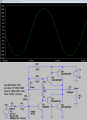
Works fine for me (below).
The only change I made was to change to the non-C versions of the transistors since I didn't have the C model, but all that should do is change the transistor maximum voltage rating.
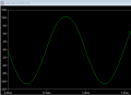
Works fine for me (below).
The only change I made was to change to the non-C versions of the transistors since I didn't have the C model, but all that should do is change the transistor maximum voltage rating.
I don't have models of TIP transistors so I used similar Japanese one in the LTspice library.
I used Sziklai pairs instead of darlingtons, added bootstrapping and AC and DC negative feedback:
What have you expected if you without any critical thinking substitute values into the formula?
First of all, your amplifier circuit is supplied from a single supply (30V). It should be obvious to you that it is impossible to get 30V peak at the output form 30V single supply. The theoretical maximum you can get is 15Vpeak for ideal push-pull amplifier. To gest more power you need a bridge amplifier https://www.allaboutcircuits.com/te...ge-amplifiers-for-single-supply-applications/
But in your circuit, the voltage swing is limited by the first CE amplifier stage. Have you done any calculations?
Let us try to do a rough calculation and find the Q1 collector voltage when Q1 is in saturation.
Ic1_sat ≈ (30V - 0.2V)/(1.7kΩ+ 220Ω) ≈ 15.5mA and the voltage at colector will be equal to Vc1_sat ≈ 30V - 15.5mA*1.7kΩ ≈ 3.65V
Therefore the maximum negative voltage swing at the output is Vmax_neg_swing = VcQ1 - Vc1_sat = 9.36V - 3.65V = 5.7V
For Vin_max = 5.7V/(1.7k/0.22kΩ) = 0.74V
As you can see even this super simplified calculation clearly shows that it is impossible to get 15V peak at the output.
The best we can get is 5.7V peak so, the maximum output power is 5.7V^2/16Ω = 2W
I ran the crutschow2 sim with my 31C and 32C models and got an even worse
result. I guess my models are incorrect. Where can a person get reliable
models?
 Facebook
 Google
 GitHub
 Linkedin
 7.9 KB Views: 12