Facebook
 Google
 GitHub
 Linkedin
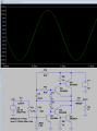
Try this
And can you show us your model?.MODEL TIP31C NPN(IS=1.62181E-13 ISE=1.75416E-11 ISC=4.36516E-14 XTI=3 BF=83.6 BR=20.607 IKF=6.98433 IKR=0.997156 XTB=1.5301 +VAF=110.5 VAR=159.374 VJE=0.636 VJC=0.408 RE=0.56 RC=0.96 RB=164.793 RBM=0.100291 IRB=1.24287E-7 CJE=4.77E-10 CJC=7.29E-11 +XCJC=0.589205 FC=0.5 NF=0.9899 NR=0.989511 NE=1.95 NC=1.014 MJE=0.327 MJC=0.339 TF=2.3733E-8 TR=1.0000E-8 ITF=1 VTF=10 XTF=10 EG=1.1605 VCEO=100 ICRATING=3 MFG=TEXAS)
.MODEL TIP32C PNP(IS=6.77594E-13 ISE=1.31133E-11 ISC=1.31133E-11 XTI=3 BF=198.8 BR=25.4966 IKF=0.891251 IKR=0.410482 XTB=1.2648 +VAF=77.429 VAR=70.9603 VJE=0.59 VJC=0.5 RE=0.06 RC=0.16 RB=161.0 RBM=3.097 IRB=3.548134E-5 CJE=2.7E-10 CJC=1.07E-10 +XCJC=0.589205 +FC=0.5 NF=1.001 NR=1.004 NE=1.98 NC=1.12 MJE=0.319 MJC=0.352 TF=2.3733E-8 TR=1.0000E-8 ITF=1 VTF=10 XTF=10 +EG=1.0863 VCEO=100 ICRATING=3 MFG=TEXAS)