Facebook
 Google
 GitHub
 Linkedin
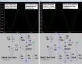
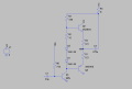
Here's a better design that uses a differential input to provide both DC negative feedback to stabilize the output bias, and AC negative feedback to determine the gain and reduce distortion.
It also has a bootstrap driver to R12, to increase the positive output drive voltage before clipping.

It also has a bootstrap driver to R12, to increase the positive output drive voltage before clipping.
Attachments
-
5.3 KB Views: 14