Class AB Amp With Class Driver

Thread Starter

newbie2019

Joined Apr 5, 2019
95
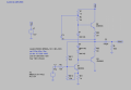
I found the following circuit online. Like most circuits found online or in textbooks,
it does not work. I know how to design a simple class ab amplifier but can't find
out how to add the class driver to the design. Note: I added the two .33 Ω emitter resistors to prevent thermal runaway. Later I would add negative feedback.
 

Attachments

crutschow

Joined Mar 14, 2008
34,469
To start with, the DC bias is off.
The voltage at the output to C2 should be about 1/2 the supply voltage or 6V.
Try reducing the value of RB11 from 100kΩ to about 35kΩ.
 

Thread Starter

newbie2019

Joined Apr 5, 2019
95
To start with, the DC bias is off.
The voltage at the output to C2 should be about 1/2 the supply voltage or 6V.
Try reducing the value of RB11 from 100kΩ to about 35kΩ.
Thanks man that did the trick. The THD is like 1.8%. Where would I add the circuitry
for the negative feedback? Or is there feedback provide by deriving the Q1 base
bias from the output?
 

Zeeus

Joined Apr 17, 2019
616
Thanks man that did the trick. The THD is like 1.8%. Where would I add the circuitry
for the negative feedback? Or is there feedback provide by deriving the Q1 base
bias from the output?
Let's start with this..not nice gain

and bandwith calculation is fun but can't do : learning

you understand circuit?

oh and change the output transistors (they are not on spice )..3904 and 06 not good for output yeah but TIP not on spice


what's THD? and that Vcc sign..Please how did you do it?

Thanks
 

Attachments

Last edited:

Zeeus

Joined Apr 17, 2019
616
You add this command and then look for the results in
View -Spice Error Log.

View attachment 179653


Vcc is simply the added NET (node) name for the power supply rail.
Any node with that name is connected together.
what's the THD for? sorry

and yeah it's node but how to add?

like want to create a node name like "Vas" which is 4V then connect to different points but don't know how to create it

edit : think I see how to do now

Also, please view this
https://forum.allaboutcircuits.com/...-analog-circuits-designs.160671/#post-1403366

Thanks
 
Last edited:

crutschow

Joined Mar 14, 2008
34,469
Where would I add the circuitry
for the negative feedback? Or is there feedback provide by deriving the Q1 base
bias from the output?
No, that provides only DC (bias) feedback.
Any AC feedback is shunted to ground by he zero source impedance.

To get some AC feedback, add a 5k resistor in series with the input source, and add a 1000uF cap from the emitter of Q1 to ground (to keep the overall gain about the same).
That should drop the distortion to about 1%.
 

crutschow

Joined Mar 14, 2008
34,469
what's the THD for?
It's Total Harmonic Distortion of the output signal (a measure of it's accuracy as compared to the input).
like want to create a node name like "Vas"
Go to Edit / Label Net, write in the net name, and then attach it to all the nodes that you want connected with that name.
The Port Type puts a box around the name if you want, such as In or Out.

upload_2019-6-13_17-1-40.png
 

Zeeus

Joined Apr 17, 2019
616
It's Total Harmonic Distortion of the output signal (a measure of it's accuracy as compared to the input).
Go to Edit / Label Net, write in the net name, and then attach it to all the nodes that you want connected with that name.
The Port Type puts a box around the name if you want, such as In or Out.

View attachment 179654
okay..give you like...
Please go here and give expert answer
Thanks
https://forum.allaboutcircuits.com/...-analog-circuits-designs.160671/#post-1403366
 

Jony130

Joined Feb 17, 2009
5,488
class AB but with a vbe multiplier. It doesn't work worth a hoot.
But how would adding the Vbe-multiplier will improve the amplifier? Do you know what Vbe-multiplier was supposed to do in this circuit?

Try to read this very cerfully
https://electronics.stackexchange.c...er-gain-than-input-and-distorte/262302#262302
https://electronics.stackexchange.c...ng-out-the-bottom-of-this-push-pull-amplifier
https://electronics.stackexchange.c...t-buffer-for-low-current-op-amp/330205#330205
http://www.circuitbasics.com/design-hi-fi-audio-amplifier-lm3886/
 
Last edited:

Zeeus

Joined Apr 17, 2019
616
Seems you have something new every time
This circuit, dc output is not Vbe ?

About to read properly
 

Attachments

crutschow

Joined Mar 14, 2008
34,469
Here is another class AB but with a vbe multiplier.
That's just a transistor to generate a bias voltage that takes the place of the two diodes in the first circuit.
You can replace the two diodes in that circuit with the transistor and two associated resistors, but I see no particular advantage of the transistor over the diodes.

The two dodes have the advantage in that there combined temperature coefficient will roughly match the output transistors' temperature coefficient if the diodes are glued to the transistor housings.
That helps keep the bias current constant as the transistors heat up.
 

Jony130

Joined Feb 17, 2009
5,488
The two dodes have the advantage in that there combined temperature coefficient will roughly match the output transistors' temperature coefficient if the diodes are glued to the transistor housings.
But Vbe-multiplier can also do that. Because Vbe-multiplier not only multiplies the Vbe voltage but also the transistor temperature coefficient.
 
Top