circular polarized patch antenna multi resonances logic

Thread Starter

yef smith

Joined Aug 2, 2020
717
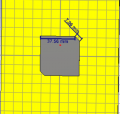
Hello,In microstrip antenna with circular polarization we have a situation where we have multiple resonances depending on the frequency as shown bellow.
Is there some detailed explanation explanation on how those resonances are formed?
and why we have 90 degree phase in the interpsection point between the hills?
Thanks.
1632066806704.png
1632066757945.png
 

Tesla23

Joined May 10, 2009
542
The patch isn't square and so there are two modes that are close to resonance. For CP we want the radiated fields 90 deg apart. Why don't you try to work out from the location of the feedpoint, and the fact that the patch isn't square, what the phase difference between the two modes is?
 

Thread Starter

yef smith

Joined Aug 2, 2020
717
Hello Tesla23, I have tried to implement your words into actual CST simulation.
As you can see bellow the is a coaxial cable which acts for pin feeding as shown bellow.
on the coaxial pin feeding i have defined waveguide port as shown bellow.
then i looked at the far field plot of each electric field mode as you can see bellow.
The field lines of the modes are not perpandical to each other as shown bellow.
Also CST says that these are TEM modes instead of TM for some reason.
also i tried to look at the Z-parameter plots.where i was supposed to see the two hills from the manual with the intersecting point,i only saw one hill.
Where did i go wrong?
Why my modes are not perpandicaluar to each other?
Thanks.

1632157026812.png
1632157608381.png
1632160633144.png
1632160692799.png
1632160804670.png
1632160918171.png
1632161029052.png
1632161053688.png
 

Tesla23

Joined May 10, 2009
542
Hello Tesla23, I have tried to implement your words into actual CST simulation.
Then read them again, and your initial post. Also, whatever happened to analysis, rather than just plugging stuff into CST?

If you can't figure it out, here's a good reference:
W. Richards and Y. Lo, "Design and theory of circularly polarized microstrip antennas," 1979 Antennas and Propagation Society International Symposium, 1979, pp. 117-120
 
Last edited:

Thread Starter

yef smith

Joined Aug 2, 2020
717
Hello Tesla 23,I have taken a working CP patch antenna with trimmed edges as shown bellow.
The Axial ratio plot is as shown bellow also the rotation of far field plot.
The feeding is not in diagonal but in the middle.

I have tried to analyze this model using the formula taken from the article you reccomended using the measures of the model shown bellow.

Using the matlab code shown bellow i got only 1.5 degree phase shift(not radians)
also my Z11 doent have 90 phase in f=2.3314Ghz

So why Its workig , Where did i go wrong with implementing this formulla or understanding the Z11 data?
Thanks.

7.06/sqrt(2)=5
a=42.56;
a_t=37.56;
k2=2*(a-a_t)/(pi*a);
cof=pi*(a-a_t)/a;
phase_diff=k2*sin(cof);
phase_diff_deg=(180*k2*sin(cof))/pi;
1.5459

1632408961441.png
1632417780081.png
1632417664444.png
1632422941343.png
1632423192986.png
1632423243521.png
 

Attachments

Top