Circuit to thermostatically control manual vehicle aircon system

Sapote

Joined Apr 27, 2023
13
I would disagree with the notion that an automatic climate control type of AC would be less wasteful, as with these systems people tend to have them operating continuously, whereas I find that with a manual system I only really switch it on when it gets uncomfortably warm, and switch it off once it has cooled the cabin down a bit.
Does your idea of good economic also apply to home AC system without Tstat?
If I add thermostatic control to mine it will probably mean that it will be operating more!
So you're saying your skin is more precise than the Tstat of sensing the temperature?
Let's say you want to set it to 75F, you would turn it off as soon as it gets to 76F as compared to the Tstat turns it off at 75F (and turn back on at 76 or 77F with hysteresis). Can you tell it's 76F or 74F to turn it off? No way that you are better than the controller with Tstat feedback.
 

Sapote

Joined Apr 27, 2023
13
I am pretty sure there is no thermostatic control and in fact it appears that the dials operate cables to remotely adjust airflow and control hot water flow, so they would need to be motorised if there was any thermostatic control, which they definitely aren't.
What needs to be motorized in order to use a Tstat feedback? The same control dial can move the air flaps for the AC mode, so I don't understand about the need for motorization.

Does the dial have a wide section for blue as much as for the red section? I just want to confirm if the dial blue zone is not just a binary to set the fresh air or not, but also have a range of temperature setting range.
I still think your existing system does have cold AC temperature setting. If it has temp setting, then it must have Tstat feedback.
 

Thread Starter

fred_jb

Joined Jul 13, 2024
41
I think this thread is going way off track so I won't be responding any further to interrogations regarding my system and my reasons for modifying it as it seems like every answer I give generates three more questions!

Any contributions to the original technical question are of course still welcome.
 

DNA Robotics

Joined Jun 13, 2014
670
The red section of the dial permits varying rates of hot water flow and when you go into the blue section the heating water flow is stopped and you just get ambient temp air flow unless you turn on the AC. I am pretty sure there is no thermostatic control and in fact it appears that the dials operate cables to remotely adjust airflow and control hot water flow
A lot of cars use air mix doors instead of variable water flow valves.
I suggest that the dial permits varying rates of cooling as well.
If you don’t turn the dial all the way into the blue, it won’t be as cold.
 

Thread Starter

fred_jb

Joined Jul 13, 2024
41
I have not had much luck with analysing the voltages on, and the resistances between, wires which connect the AC switch which I think is probably due to some circuitry inside the housing. My next move is to open up the housing to get direct access to the AC switch and LED contacts. I have managed to source a secondhand housing quite cheaply to practice on!

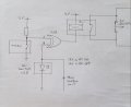
In the meantime I have been giving some more thought to an interface circuit and would be very grateful if anyone could point out the inevitable fatal logical flaw in the circuit I have come up with! I do realise that there would probably need to be some sort of buffer between the logic gate output and the relay coil, so if the circuit would otherwise work, suggestions for that would be welcome.

20240719_151622.jpg
How I think this would work is as follows:

When the ignition is first switched on the thermometer relay will be open and so input A will be high and I believe the thermometer can be programmed to have a switch on delay before it will operate the relay so this condition can be made to persist for a few seconds. Input B from the switch LED will be either low or high depending on whether the AC was on last time the ignition was switched off. If it was off B is low and the output of the XOR gate is high so the relay does not operate. If it was on, B is high and the gate output is low, switching RL1 and activating the AC switch. This then turns off the LED and puts input B low which forces the output of the gate high so the RL1 stops operating and its contacts open.

When the thermometer delay expires and if it then demands cooling and closes its relay, input A is then low and input B is also low having been previously switched off as above. This puts the output of the gate low which activates RL1 and turns the AC on. This turns on the LED which puts input B high and the gate output goes high switching off the relay, leaving the AC running.

When the set temperature is reached the thermometer relay opens putting input A high which together with input B being high because the AC LED is at that point on, sets the gate output low which operates the relay to turn the AC off.
 
Last edited:

MisterBill2

Joined Jan 23, 2018
27,759
I have not had much luck with analysing the voltages on, and the resistances between, wires which connect the AC switch which I think is probably due to some circuitry inside the housing. My next move is to open up the housing to get direct access to the AC switch and LED contacts. I have managed to source a secondhand housing quite cheaply to practice on!

In the meantime I have been giving some more thought to an interface circuit and would be very grateful if anyone could point out the inevitable fatal logical flaw in the circuit I have come up with! I do realise that there would probably need to be some sort of buffer between the logic gate output and the relay coil, so if the circuit would otherwise work, suggestions for that would be welcome.

View attachment 327337
How I think this would work is as follows:

When the ignition is first switched on the thermometer relay will be open and so input A will be high and I believe the thermometer can be programmed to have a switch on delay before it will operate the relay so this condition can be made to persist for a few seconds. Input B from the switch LED will be either low or high depending on whether the AC was on last time the ignition was switched off. If it was off B is low and the output of the XOR gate is high so the relay does not operate. If it was on, B is high and the gate output is low, switching RL1 and activating the AC switch. This then turns off the LED and puts input B low which forces the output of the gate high so the relay closes.

When the thermometer delay expires and if it then demands cooling and closes its relay, input A is then low and input B is also low having been previously switched off as above. This puts the output of the gate low which activates RL1 and turns the AC on. This turns on the LED which puts input B high and the gate output goes high switching off the relay, leaving the AC running.

When the set temperature is reached the thermometer relay opens putting input A high which together with input A being high because the AC LED is at that point on, sets the gate output low which operates the relay to turn the AC off.
The drawing is making a guess that one side of the light in the AC button is grounded. That is quite a leap of trust.
 

Thread Starter

fred_jb

Joined Jul 13, 2024
41
The drawing is making a guess that one side of the light in the AC button is grounded. That is quite a leap of trust.
I have measured what seems to be the power line to the LED and is at 12V when the LED is lit and a fraction of a volt when off. Will be able to check this out once I get inside the unit.

Does it really matter if I am just getting an input from the anode end?
 

MisterBill2

Joined Jan 23, 2018
27,759
No, what would matter would be if neither end was available because they went internal inside the module.Like if the LED had a current regulator inside the module.
 

Thread Starter

fred_jb

Joined Jul 13, 2024
41
It is fairly evident that the actual switch is momentary from the way it works, but I can confirm that once I take apart my spare unit. The output of the relay is effectively momentary because the feedback of the resulting change of LED state into the system turns it off shortly after it is turned on.
 

sghioto

Joined Dec 31, 2017
8,688
It is fairly evident that the actual switch is momentary from the way it works, but I can confirm that once I take apart my spare unit. The output of the relay is effectively momentary because the feedback of the resulting change of LED state into the system turns it off shortly after it is turned on.
Yes I see how that works now, very nice.
 

crutschow

Joined Mar 14, 2008
38,584
It is fairly evident that the actual switch is momentary from the way it works, but I can confirm that once I take apart my spare unit. The output of the relay is effectively momentary because the feedback of the resulting change of LED state into the system turns it off shortly after it is turned on.
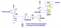
Here's a schematic of the circuit with the added needed driver for the relay:
Edit: Reversed R1 and Thermostat due to signal inversion due to transistor.

1721487691164.png
 
Last edited:

crutschow

Joined Mar 14, 2008
38,584
Thanks for that addition and the much nicer drawing!
Note correction to circuit due to signal inversion from the added transistor.
I was thinking that I would need a PNP transistor for this as it needs to switch on a low logic level. Is that not necessary?
The NPN will work fine with the change in the thermostat connection.

But if you prefer, here's the circuit with a PNP:

1721488269603.png
 
Last edited:

Thread Starter

fred_jb

Joined Jul 13, 2024
41
Note correction to circuit due to signal inversion from the added transistor.
The NPN will work fine with the change in the thermostat connection.

But if you prefer, here's the circuit with a PNP:

View attachment 327407
I will go with that as I could be wrong but I don't think the logic interaction with the LED signal works if the thermostat gives a low for open and a high for closed.
 

crutschow

Joined Mar 14, 2008
38,584
I don't think the logic interaction with the LED signal works if the thermostat gives a low for open and a high for closed.
In my post #72 circuit, when the thermostat contacts are closed for cooling, the output is high and the LED is ON, so U1's output is low and the relay is not activated.
 
Last edited:

Thread Starter

fred_jb

Joined Jul 13, 2024
41
In my post #72 circuit, when the thermostat contacts are closed for cooling the output is high and the LED is ON, so U1's output is low and the relay is not activated.
OK, having worked through this it looks like the inversion on the output of the gate does compensate for the reversal of the thermostat output so either way should work. Thanks for your input.

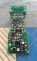
BTW, I have now dismantled the spare heater control unit which turns out have a lot of circuitry between the connector and the button and associated LED. The good news is that it is definitely a momentary switch and both contacts are accessible to attach wires for my relay, and it seems that it should also be possible to connect to the LED via a test pad on the underside of the board.

The switch is the square black component at centre bottom in the picture.


20240720_164458.jpg
 

crutschow

Joined Mar 14, 2008
38,584
it should also be possible to connect to the LED via a test pad on the underside of the board.
You need to measure the LED voltage you want to tap for both it being off and being on.
Likely that's only about 2-3V.
The voltage you want may be on the resistor in series with the LED that limits its current (if it has one).

If not, then you may need an added transistor to convert the low LED voltage to the 12V required by the XOR gate input.
 

Thread Starter

fred_jb

Joined Jul 13, 2024
41
You need to measure the LED voltage you want to tap for both it being off and being on.
Likely that's only about 2-3V.
The voltage you want may be on the resistor in series with the LED that limits its current (if it has one).

If not, then you may need an added transistor to convert the low LED voltage to the 12V required by the XOR gate input.
Thanks. Yes good point. What I intended doing was connecting the circuit board from the scrap panel to the connector which normally connects to the same panel in the van. That will make it live and I can then probe for a suitable signal source.
 
Top