I am talking about the vehicle aircon built into the vehicle dashboard, the equivalent of the aircon in a car, so will be 12V. Unfortunately it is not the more sophisticated climate control type, but just a basic manual system controlled with an ON/OFF button, hence why I would like to control it with a thermostat while driving.I'm confused.
Campers often have a separate, mains powered AC, so does this AC run from mains voltage or the engine?
The thermostat module allows the hysteresis, that is the difference between on and off temperatures, to be set over a wide range, so I will probably set it to about 3 degrees initially which should avoid excessive cycling.What temperature difference will you be using to determine shutoff and startup?? That affects how often the system cycles between cooling and not cooling. Do you really want the system stopping and starting as the temperature varies one or two degrees??
Then it would seem just switching the current to the compressor clutch as already suggested would work, no additional circuitry required, only likely an added relay.I am talking about the vehicle aircon built into the vehicle dashboard, the equivalent of the aircon in a car,
Well that's as may be, but I would be concerned about an uncommanded deactivation of the clutch being detected as a fault by one of the various electronic control modules in the vehicle, causing a fault code to be registered with the main ECU. I always try to avoid any mod potentially detectable by the electronics when modifying my vehicles, and this policy has been successful in avoiding problems on various motorcycles and other vehicles so I will stick by it as far as possible.Then it would seem just switching the current to the compressor clutch as already suggested would work, no additional circuitry required, only likely an added relay.
I doubt anything monitors the clutch voltage/current, but it would be easy to test by just disconnecting the clutch wire when the AC is on, and see if there's an error generated.about an uncommanded deactivation of the clutch being detected as a fault by one of the various electronic control modules in the vehicle,
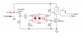
Thanks for that, but can you explain how it works to produce a momentary output both when the thermostat relay closes and also when it opens?Another circuit to activate the Control Button.
View attachment 326938
Sure.Thanks for that, but can you explain how it works to produce a momentary output both when the thermostat relay closes and also when it opens?
Since the opto provides isolation you likely could do away with the relay and connect the transistor across the AC switch (observing the switch voltage polarity of course).With the right relay Q1, R3 and R4 can be eliminated.
Possibly, if we knew what current is required.Since the opto provides isolation you likely could do away with the relay and connect the transistor across the AC switch (observing the switch voltage polarity of course).
I would expect it to be a low-current logic signal to the vehicle's computer.Possibly, if we knew what current is require.
I agree but would want validation on that before damaging anything. The TS will have to check that out first.I would expect it to be a low-current logic signal to the vehicle's computer.
I would not leave out the relay because with a PB there is a definite flat low resistance with contact bonce, while the opto resistance does not go that close to zero.Possibly, if we knew what current is required.
Yes, the opto output directly may not have a low enough resistance.I would not leave out the relay because with a PB there is a definite flat low resistance with contact bonce, while the opto resistance does not go that close to zero.
It would also help if you can get voltage readings on both sides of that ON/OFF switch.First I need to get access to the wiring to the AC ON/OFF switch to see how it connects, though I am already certain that it is not a latching switch.
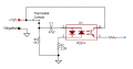
We have no hint or clues as to what is connected to either side of that PB "switch" device. Thus the 12 volt connection shown totally defeats the opto-isolation.I thought you were speaking of the opto as well.
It could be as simple as this:
View attachment 327013
That is correct which was my request in post #37.We have no hint or clues as to what is connected to either side of that PB "switch" device. Thus the 12 volt connection shown totally defeats the opto-isolation.