Short on thought but a second RC circuit ( 1M & 1000uF ? ) both feeding into a comparator. Delayed output on sunrise = sun rise. might need some ANDs & more comparators.
I feel a need to apologize for some of the comments.
But beyond that, while your question is clear, you have not thought it all the way through. From the point of view of a single sensor circuit, sunrise and sunset are transient events, moments in time when the environment changes from one steady state to the other. Day and night are the two steady states. A LDR and one comparator will give you a signal that is (for example) high during daytime and low during nighttime. When properly adjusted, the illumination when the circuit output changes state will be in the middle of the transition periods when night is transitioning into day (sunrise) and vice versa. So one comparator gives you four signals:
Positive-going edge: sunrise
Steady state high: daytime
Negative-going edge: sunset
Steady-state low: night
It is up to the downstream circuits or PIC to interpret and act on these conditions.
The next layer of complexity could be one of several options, such as have the circuit make a pulse output during sunrise and sunset. Or, with the window comparator mentioned above, have a signal line that is high only during the sunrise period between full nighttime and full daytime.
Saying that you want to "detect states" is not enough. Expand your description of how you want the circuit to behave, how many output signals you want (such as separate signals for day and night), and what downstream circuits these signals are going to drive.
Hi thank you soo much the window detector is what i needed but it pluses high (11) for both charging and discharging (output pins of both opamps are not connected). I want to be able to distinguish between the pulses give charging 00 and discharging 11.
Ive realised a pattern of both output pins
output pin 1: 1101
output pin 2: 0111
when the capacitor is not charging it is 10 and fully charged is 01
Any tips will be appreciated
ive attached a picture from a youtube video that i used to help me understand window detectors...
Hi how can I use the window comparator to do detemine if the last state was dark or light . I initially left the two outputs of the window comparator open to do this but I get weired simulation results. My simulation results are not similar to the pictures I uploaded
This is the circuit im using I found it on YouTube but I havnt used the LEDs
If you want to know the last state (day or night), then you need a latch. But if you want to know the current state, the two individual window comparator outputs (before they are combined) show the day/night state.
A very common way to grow a window comparator is with two open-collector-output comparators, such as two sections of an LM393 or LM339. Because they are open-collector outputs, they can be tied together directly to a single pull-up resistor to form the "window" signal.
BUT, if you use opamps instead, and combine the outputs through diodes (a diode-OR or diode-NOR circuit), then the separate outputs before the diodes are steady-state day and night signals.
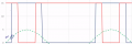
Below is a schematic of a LM339 comparator using two of the four comparators. They are configured as a window comparator. Vsupply in this case is 12 VDC. The lower and upper limits are 4 volts and 8 volts. The outputs are tied as Analog mentions and R4 serves as a pullup resistor since the LM339 outputs are what is known as open collector.
Here is the circuit:
Comparing Vin and Vout you can see where Vout is only on (high) while the level is inside the window. Vin is just an increasing voltage (blue trace) which gets to 12 VDC, where it sits a few seconds then decreases.
The only way to remember or recall a last state is as Analog mentions, using a latch. The more features you want the more parts you add.
Any quality photocell or LDR will include a data sheet and here is one such example. This is not true of when you buy a bucket of them off the boat for $3.00 USD per hundred. Everything is defined like the spectral sensitivity range. Anyone who was ever into photography knows morning light (sunrise) and evening light (sunset) are not in the same spectrum as high noon. While a general purpose basic CDS photocell will work for basic applications just make sure it is going to one spectrum of light with more response than another. Yes, using a photovoltaic cell is another option. Point is the end user needs to have at least a basic understanding of what is going on with any circuit they use.
If you want to know the last state (day or night), then you need a latch. But if you want to know the current state, the two individual window comparator outputs (before they are combined) show the day/night state.
A very common way to grow a window comparator is with two open-collector-output comparators, such as two sections of an LM393 or LM339. Because they are open-collector outputs, they can be tied together directly to a single pull-up resistor to form the "window" signal.
BUT, if you use opamps instead, and combine the outputs through diodes (a diode-OR or diode-NOR circuit), then the separate outputs before the diodes are steady-state day and night signals.
Hi,
im using opamps, i havnt read about LM393 so i would prefer not to use them.
why do i need to use diodes on the output if im connecting the output directly to a microcontroller?
In addtion, i only get a pulse when i connect both outputs to a logic gate (with or without a diode) but if i connect both outputs together without a logic gate i sometimes get small triangle pulses.
in addition do you mind showing me this "(a diode-OR or diode-NOR circuit)"
Below is a schematic of a LM339 comparator using two of the four comparators. They are configured as a window comparator. Vsupply in this case is 12 VDC. The lower and upper limits are 4 volts and 8 volts. The outputs are tied as Analog mentions and R4 serves as a pullup resistor since the LM339 outputs are what is known as open collector.
Comparing Vin and Vout you can see where Vout is only on (high) while the level is inside the window. Vin is just an increasing voltage (blue trace) which gets to 12 VDC, where it sits a few seconds then decreases.
The only way to remember or recall a last state is as Analog mentions, using a latch. The more features you want the more parts you add.
When i connect the outputs of both opamps together (with or without a diode) i do not get a pulse like the one in the picture you showed, only small trianle pulses during simultion.
When i connect the outputs of both opamps together (with or without a diode) i do not get a pulse like the one in the picture you showed, only small trianle pulses during simultion.
The common mode input range for LM339 goes down to ground. That won't be the case for all opamps. The output of LM393 is nearly rail to rail. Not all opamps have rail to rail outputs.
Generally a comparator operational amplifier would be used. An operational amplifier can be used but a comparator is normally the best choice since we are looking at saturated regions as in On or Off, a High or Low output with no linear region. What operational amplifier(s) did you plan to use? Reason I ask is you really want, assuming op amps, a single supply op amp which is rail to rail. A single supply rail to rail op amp could be placed in the drawing I left last post.
If this is going into a micro which micro? Placing a LDR and a resistor in series makes for a voltage divider. This has all been covered. Why not just run the analog voltage out of the divider into the ADC of the uC? Using a 10 bit ADC like most micro controllers have you simple scale it. All of this can be done simple using code so why are you wanting to use anything else since you plan to feed a micro controller? Again I'll ask which micro controller?
As to the diodes? They are used to form a diode logic AND gate or a OR gate. In the link A & B are your op amp outputs. Less the diodes what happens when one op amp goes high while the other is low? Think about the truth tables in the link.
To make a simple circuit you need to latch the last state (Almost fully dark or almost fully light.). This is what I suggest. Use two comparators. One to give a high output when it fully light. (Say 90% of maximum light reading.) The other to give a high output when it is almost fully dark. (Say 10%) The 90% one would be connected to the set input of a bistable (Latch) (Such as half of a CD4013)
The 10% one would be connected to the reset input of the latch. So at sunrise or sunset neither comparator output would be high. So for example going from light to dark (Sunset.) Between 100% and 90% the set input of the latch would be high forcing the Q output of the latch high. When the level dropped below 90% neither the set or reset input of the latch would be high so the latch remains in it's current state. (Q = high.) So if you use some logic gates to give an output when both comparator outputs are low and the latch output is high that would indicate sunset. So for sunrise you would use similar logic to give an output when neither comparator output was high and the latch NOT Q output was high. So now you have 4 outputs. Dark less than 10%. sunrise, between 10% and 90% after it being dark. Light, greater than 90%. And sunset neither comparator output was high and the latch Q output was high. Another way would be to differentiate the analogue light level signal to give an one output for a rising level and another output for a falling level. This would ve VERY difficult to do with analogue methods with such a low rate of change. It would also be sensitive to shadows passing over the detector.
I think you need to take a step back and ask some basic questions. The most important of which is why you want to detect sunrise and sunset. What is the actual problem that you are trying to solve? Are there alternative approaches that have nothing to do with detecting sunrise and sunset that might work? If you determine that you really need to detect sunrise and sunset, then you need to spend sometime defining what, for your purposes, those two terms even mean and what will constitute a failure or success in detecting them?
What happens if your detector decides it is "sunset" two hours after actual sunset today and an hour before actual sunset tomorrow? Same for sunrise? Will this cause a huge problem, or a minor inconvenience? What will happen if your detector decides that the sun rose and set three times today?
I would recommend putting something together and then logging the data for several days, preferably when there's both nice clear days and when there's a lot of weather moving through. You may find that the difference between day and night is so distinct that the weather during the day is a non-issue -- or you might find the reverse is true. I remember when we had the total eclipse last year that even though I was in a region of 90+% totality that there was no perceptible change in the ambient light (to the human eye) although the various light meters of all kinds had no problem seeing the huge difference. That might mean that the light level at night is so far down in the basement that there's a much sharper drop across the sunrise/sunset boundaries than there is for heavy cloud cover and the like.
RE: SamR - in this question seems You are not an expert. As the physicist, environmentalist, captain, astronomer (but not as electronicst) I know better as well there are a crucial difference between those states I named (why then You are not pushing the knob named Goooooooogle??), but yes, You are true that for SIMPLE tasks there are no any BIG difference between those happenings, as the seconds or worst case scenarios few minutes are staying between `em.
My intention was to understand do the author realizes that difference and do his will is exact sub-second accuracy, ot just about choice between "about dark" and "about shiny". As if the will is exact detection, it is impossible on simple light measurement techniques, but the Solar position must be measured geometrically (teleccope, AI analyser etc).
 Facebook
 Google
 GitHub
 Linkedin
")